G O M - 영 문
57
y
These flue systems may be oriented in all the possible directions: front, back, right
and left hand.
y
They may also include some special components, like the concentric bends, in
order to reach some particular position.
y
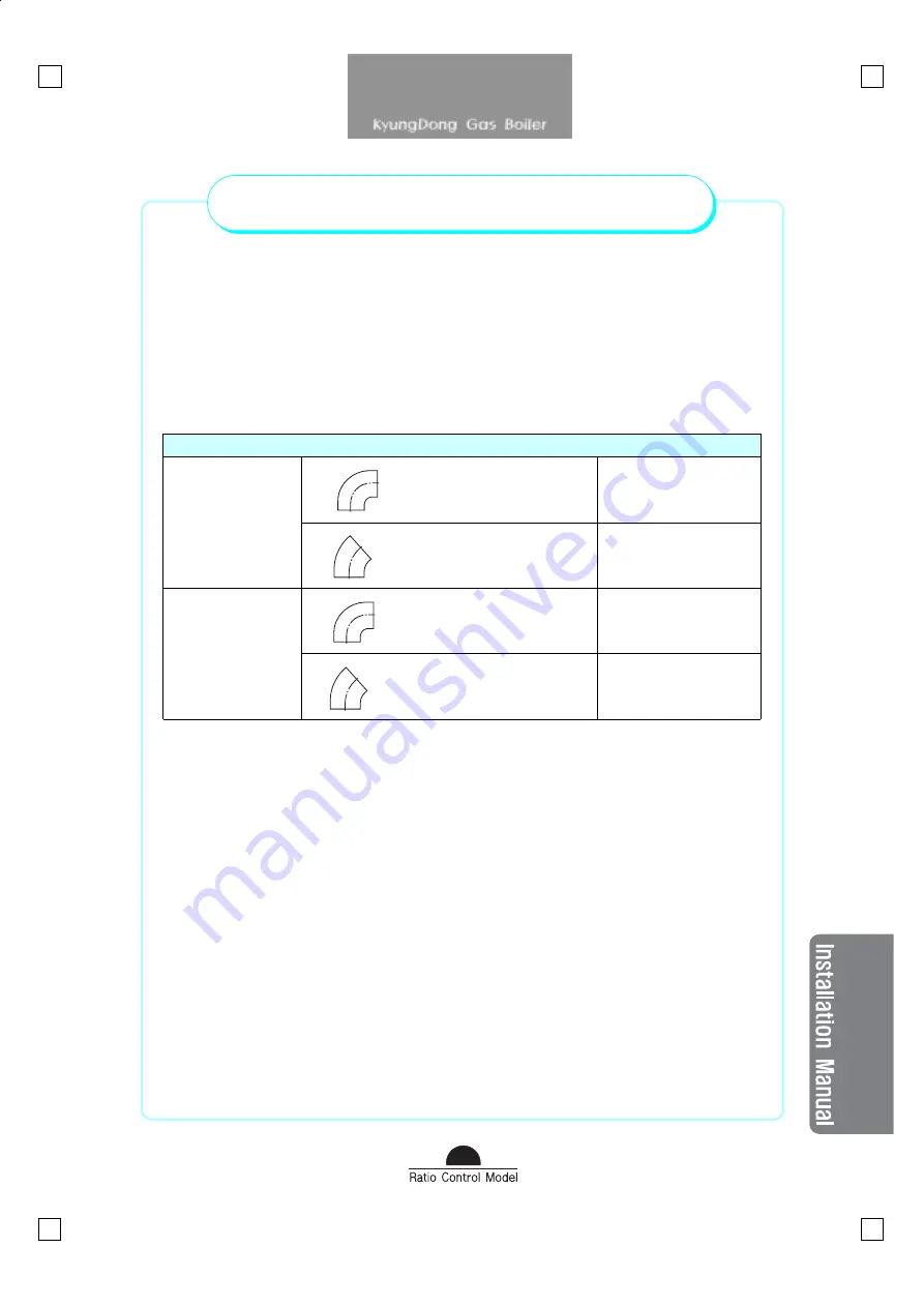
If it is necessary to insert some concentric bends, please consider that each of
them has a resistance corresponding to the following linear length :
Equivalent resistance - Reduction of length
90°
Cod. A 03.001.000276
0.6m
Bend
60/100 mm
45°
Cod. A 03.001.000746
0.5m
90°
Cod. A 03.005.000018
1.2m
Bend
80/125 mm
45°
Cod. A 03.005.000019
1.0m
y
Then, for example, if it
’
s necessary to insert one 90
°
bend in the 60/100 flue system
type C13, the total length that the horizontale flue system may reach is not 2.88m
but not more than 2.28m.
y
If it
’
s necessary to insert two 45
°
bends in the 80/125 vertical flue system type C33,
the total high that the vertical flue system may reach is not 6.70m but not more than
4.70m.
Choice of the Correct Diaphragme with the Bends Included in the Flue
System.
y
If some bend is included in the flue system, the total length for the evaluation of the
correct diaphragm has to be calculated adding the reduction of length shwoed in
the above schemes.
y
For example; if the flue system is a combination of 1.50 linear flue system type C13
plus 1 bend, the total equivalent length is 2.10m : then is not necessary to insert
any diaphgram in the boiler.
Calculation of the maximum length with the concentric
bends included in the flue system


