background image


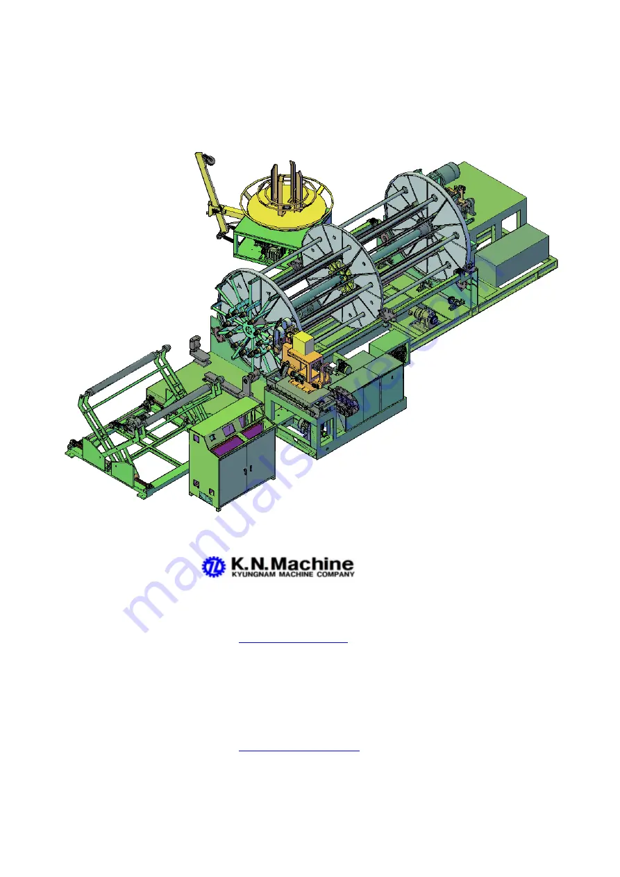
MANUAL  OF  CAGE  WELDING  MACHINE


MODEL:  KN-1248-G3


MAKER:     

                           135 SEONGJU-RI,WONGOG-MYEON

                           ANSEONG-CITY,KYUNGGI-DO,KOREA
                           TEL.:82-31-656-5385  FAX.:82-31-656-5386


                           E-mail:

knhslee@hanmail.net

             EXPORTER:     BM TRADING COMPANY
                           R00M#3304.KOREA WORLD TRADE CENTER 


                           159 SAMSUNG-DONG,KANGNAM-KU
                           SEOUL135-729,KOREA 


                           TEL.:82-2-551-2716   FAX.:82-31-272-2470
                           E-mail:

bmtrading@hanmail.net

 or bmtrading3304@yahoo.co.kr

Summary of Contents for KN-1248-G3

Page 1: ...CITY KYUNGGI DO KOREA TEL 82 31 656 5385 FAX 82 31 656 5386 E mail knhslee hanmail net EXPORTER BM TRADING COMPANY R00M 3304 KOREA WORLD TRADE CENTER 159 SAMSUNG DONG KANGNAM KU SEOUL135 729 KOREA TEL 82 2 551 2716 FAX 82 31 272 2470 E mail bmtrading hanmail net or bmtrading3304 yahoo co kr ...

Page 2: ... PRODUCTION 7 CHANGE PRODUCT SPECIFICATION 8 HOW TO MAKE CAGES 9 PROXIMITY SWITCH FUNCTION 10 ERROR DISPLAY 11 REPLACE SPARE PARTS 12 MACHINE SPECIFICATION 13 WEARING PARTS 14 ELECTRIC SEQUENCE 15 TOUCH PANEL MANUAL www lsis biz 17 TZ4ML TEMPERATURE CONTROLLER MANUAL www autonics com 18 AC FREQUENCY DRIVE MANUAL LS www lsis biz 19 P L C MANUAL LS www lsis biz ...

Page 3: ......

Page 4: ......

Page 5: ......

Page 6: ......

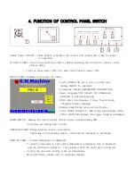
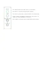
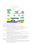
Page 7: ...ge it stays forever before changing another language Display present pipe type and specification Touch DRIVE SCREEN to make same pipe w same datas TOTAL COUNTER displays total cages made accumulated 3 AMP METER Display the current electric motors power except welding AMP All motors are driving with 20 25A 4 WELDING AMP Display welding current consumption Depending on the welding status current wil...

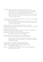
Page 8: ...sting toggle switch for height of 2 receiving rollers according to cage diameter It is moving up down as long as pushed switch but stop by touch of top bottom proximity switch Safety Switch POWER ON POWER OFF Power ON or OFF except P L C and TOUCH PANEL TOUCH PANEL can power ON but can not power OFF POWER OFF button can turn off power When POWER OFF or EMERGENCY STOP button pushed TOUCH PANEL disp...

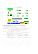
Page 9: ...ger diameter BELL REDUCE for smaller diameter It works as long as the button is pushed During the AUTO operation this button does not work Also this button is not work unless TRANSFER is backward completely Safety proximity switch is attached at end of BELL EXPAND and end of BELL REDUCE If this switch is touched TRANSFER BELL POSITION ERROR on EMERGENCY STOP INFORMATION screen is lit in red and EX...

Page 10: ...d press it again to close After 10 seconds CYLINDER opened BELL REDUCE and POLE B W will moves After CYLINDER closed push AUTO button but CYLINDER open and machine is stop if TURN TABLE is OFF Reset and TURN TABLE should be ON MANUAL WELDING Manual weld 1 point until setting welding time to secures a spiral wire to be welded on longitudinal wire firmly Push it longer time but weld with set time AU...

Page 11: ...s not working during the AUTO operation This button is working when a operator stands on the Pressure Pad During a operator are standing on Pressure Pad main panel is not works at all except EMERGENCY STOP button FOOT SWITCH on Pressure Pad can make DRUM turning clockwise ...

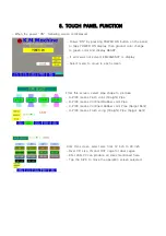
Page 12: ...ct menu to move to each screen From this screen select pipe shape to produce A PIPE means Flush Joint Straight Pipe B PIPE means Confined Rubber Joint Pipe C PIPE means Confined Rubber Joint Pipe Spigot Bent D PIPE means Flush Joing Straight Pipe Spigot Bent From this screen select size from 12 inch to 48 inch Over 36 size IN and OUT cage for dual cages KN 1248 P3 can produce all sizes mentioned h...

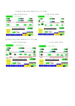
Page 13: ...Following screen shows dimension for A or B pipe A Pipe Product Screen B Pipe Product Screen Following screen shows dimension for C or D pipe C Pipe Product Screen D Pipe Product Screen ...

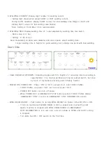
Page 14: ...as much as moved in metric mm and stop TRANSFER F W at 50 to touch Proximity Switch Last Ring During AUTO operation TRANSFER F W is stopped and weld points as much as set points from 0 to 12 Start Slow Starts slow Drum r p m and TRANSFER F W with pitch for distance set up Speed for DRUM TRANSFER BELL and POLE can not be changed randomly but green color button below Max 6000 can be changed for DRUM...

Page 15: ...CW TRANSFER bar shows Transfer Stop Transfer Slow Transfer Fast Transfer F W Transfer B W BELL bar shows Expand Reduce POLE bar shows Pole F W Pole B W Max 6000 green bar left can be set up high speed of Drum Rotating grey bar right can not set up due to low speed of Drum Rotation fixed up Max 6000 can be changed to 4000 or 5000 according to cage diameter More than 6000 can not set up for safety o...

Page 16: ...d stop TRANSFER F W at 50 to touch Proximity Switch Barrel Length Distance for high r p m of DRUM and high speed of TRANSFER DRUM is turning as per set up Hz 6000 5000 4000 and TRANSFER is moving as per set up Hz DRUM and TRANSFER will be changed to slow r p m speed before 50mm from end of Barrel Length Last Ring During AUTO operation TRANSFER F W is stopped and weld points as much as set points f...

Page 17: ... same digit when it will be selected Therefore POLE position to be set up one time only for each size so be sure to check correct digit before start Actual value of Drum Stop Bell Stop Transfer Stop Pole Stop are showing in each bar black in digit and Hz for AC Frequency drive DRUM bar shows Drum Stop Drum Slow Drum Fast Drum CCW Drum CW TRANSFER bar shows Transfer Stop Transfer Slow Transfer Fast...

Page 18: ... turning as per set up Hz 6000 5000 4000 and TRANSFER is moving as per set up Hz DRUM and TRANSFER will be changed to slow r p m speed before 50mm from end of Barrel Length Last Ring During AUTO operation TRANSFER F W is stopped and weld points as much as set points from 0 to 12 Start Slow Starts slow Drum r p m and TRANSFER F W with pitch for distance set up Speed for DRUM TRANSFER BELL and POLE ...

Page 19: ... same digit when it will be selected Therefore POLE position to be set up one time only for each size so be sure to check correct digit before start Actual value of Drum Stop Bell Stop Transfer Stop Pole Stop are showing in each bar black in digit and Hz for AC Frequency drive DRUM bar shows Drum Stop Drum Slow Drum Fast Drum CCW Drum CW TRANSFER bar shows Transfer Stop Transfer Slow Transfer Fast...

Page 20: ...RUM and high speed of TRANSFER DRUM is turning as per set up Hz 6000 5000 4000 and TRANSFER is moving as per set up Hz DRUM and TRANSFER will be changed to slow r p m speed before 50mm from end of Barrel Length Last Ring During AUTO operation TRANSFER F W is stopped and weld points as much as set points from 0 to 12 Start Slow Starts slow Drum r p m and TRANSFER F W with pitch for distance set up ...

Page 21: ...are showing in each bar black in digit and Hz for AC Frequency drive DRUM bar shows Drum Stop Drum Slow Drum Fast Drum CCW Drum CW TRANSFER bar shows Transfer Stop Transfer Slow Transfer Fast Transfer F W Transfer B W BELL bar shows Expand Reduce POLE bar shows Pole F W Pole B W Max 6000 can be changed to 4000 or 5000 according to cage diameter More than 6000 can not set up for safety of machine R...

Page 22: ...L Hz TRANSFER Hz POLE Hz의 FREQUENCY Hz Shows present Hz MANUAL SETTING Hz for each part can be set up for MANUAL DRIVE Note This Hz setting value is working at MANUAL DRIVE only and it is not effect to AUTO drive screen MANUAL DRIVE All button in MANUAL DRIVE is working as loong as pushed as same function of buttons on MAIN PANEL Each part Yellow color bar change to Red color bar at time of stop b...

Page 23: ...o touch F W stop Proximity Switch and touch CONFIRM to make Encoder value 0 and POP UP is disappeared Main reason of Encoder value 0 is touched Proximity Switch by a wire or steel material This red bar to select Pole Encoder NO USE When Pole Encoder is using in the operation Pole is moving according to Pole Position showing on Drive Screen However Pole Position value have a tolerance due to Back L...

Page 24: ...ved Products for each pipe type A B C D are recorded Touch RESET bar for each type pipe to delete quantity and shows 0 If touch digit beside of A B C D the digit became 0 If touch individual bar of digit it became 0 only TOTAL quantity can not be cleared ...

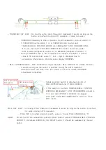
Page 25: ...1 3 In case of Safety Sensors are installed People or material is interrupted sensor 4 TRANSFER BELL POSITION CHECK Proximity Switch is touched when Transfer forward or backward or Bell Limit Proximity Switch Backside is touched Pole is not moving unless Bell is moving 5 WATER TEMPERATURE HIGH Cooling water temperature is over the temperature set up by TEMPERATURE CONTROLLER on the panel Waits tem...

Page 26: ...rol panel Frequency Driver should be replaced After replacement of new Frequency Driver set up Parameter as per Parameter Setting 8 PLC BATTERY CHECK P L C Battery should be replaced Battery should be replaced with Power ON by open cover of CPU Failure of changing Battery in this time built in program is cleared to stop operation Normally Emergency Stop trouble would be release by touch RESET bar ...

Page 27: ...age Set up dimension is smaller than actual size expand diameter by BELL EXPAND Pole is forward automatically so do not need to push POLE F W button 6 Push POLE F W button until 5mm gap of back cylinder and set up Pole Position same value showing in Green Color bar left When you set up value for Pole Position Barrel Size and Bell Size RESET button should be pressed and entered 7 Set up all other d...

Page 28: ...dies shield wires etc 14 Electricity of all driving motors are 220 Volts except welder 480 Volts Tolerance is 10 Over tolerance makes welding controller and transformer damaged Proper operation temperature is 5 40 C 23 104 F During winter time under 10 C 14 F a glow lamp 100W inside control panel and welding controller will be recommended for warmer Clean panel inside and Inverter cooling fan by a...

Page 29: ...gap of back cylinder If Touch Screen have correct set up chart already push AUTO BACK button 5 Set up new value on Touch Screen 6 Adjust SLOW and FAST welding volume by volume dial on Control Panel 7 Adjust wire guide roller to make a round circle 8 Insert rest 10 longitudinal wires to make 12 longitudinal wires 9 Adjust height of cage receiver 10 Push MANUAL WELDING button to weld 1 2 points and ...

Page 30: ... pitch because Transfer is not moving before welding points set up digit Last Ring makes last bell bottom spiral wire pitch because Transfer is stopped but welds more points set up digit and stop Drum rotating Narrow pitch for less Ring count and wider pitch for many Ring count 3 Input Start Slow Length 4 Input Last Slow Length If input Start Slow Length and Last Slow Barrel length is input automa...

Page 31: ...just Wire Guide Holder 4 5 for round spiral wire 12 Push DRUM ROTATING button to be positioned at Welding Point B 13 Push CYLINDER button to close Cylinder to contact spiral wire to longitudinal wire 14 Adjust air pressure of 7 and 8 Air pressure should be adjusted according to longitudinal and spiral wire diameter Example 5mm Longitudinal wire x 6mm Spiral wire 7 Air pressure 5 bar 8 Air pressure...

Page 32: ...h area and Drum Transfer and Welding is fast for Barrel area and slow moving for Last Slow area After Transfer is stopped Last Ring welds few points as per set up digit and Transfer fast backwards after 4 seconds later and slow down from 100mm before the end of total length If Transfer return back completely Transfer bar of Return Complete became green color 19 Opens Cylinder and cut a spiral wire...

Page 33: ...ause Transfer is not moving before welding points set up digit Last Ring makes last bell bottom spiral wire pitch because Transfer is stopped but welds more points set up digit and stop Drum rotating Narrow pitch for less Ring count and wider pitch for many Ring count 3 Input Start Slow Length 4 Input Bell Length 5 Input Leg Length After input Start Slow Length Bell Length Leg Length Barrel Length...

Page 34: ...ell Size BELL Expand as much as desired diameter and P X Switch 1 moved and fixed screw If Bell Length is short speed of Bell and Pole is running fast If Bell Length is long speed of Bell and Pole is running slow 11 Push AUTO BACK button for Bell and Pole to be returned back completely 12 Input Leg Length Actual Leg Length to be displayed 50 mm because of wire die and welding gap 13 Push BELL EXPA...

Page 35: ...m effect to Wire Drum speed Fast Drum r p m makes WIRE DRUM ERROR 21 Push MANUAL WELDING button 22 Push AUTO button to run machine in automatic operation After Welding Start Ring points set up Drum and Transfer is moving slow for Start Slow Length area and Drum Transfer and Welding is fast for Barrel area and slow moving for Last Slow area Before 50mm end of Barrel Length Drum Transfer and Welding...

Page 36: ...iral wire pitch because Transfer is not moving before welding points set up digit Last Ring makes last bell bottom spiral wire pitch because Transfer is stopped but welds more points set up digit and stop Drum rotating Narrow pitch for less Ring count and wider pitch for many Ring count 3 Input Start Slow Length 4 Input Bell Length 5 Input Leg Length Actual operation show 50 from set up digit 6 In...

Page 37: ...lete became green color If any one bar of them in not green color START ERROR will be happened 14 Push WIRE DRUM ON button and adjust Wire Guide Holder 4 5 for round spiral wire 15 Push DRUM ROTATING button to be positioned at Welding Point B 16 Push CYLINDER button to close Cylinder to contact spiral wire to longitudinal wire 17 Adjust air pressure of 7 and 8 Air pressure should be adjusted accor...

Page 38: ...rrel area and slow moving for Last Slow area Before 50mm end of Barrel Length Drum Transfer and Welding is changed slow speed After Transfer is stopped Last Ring welds few points as per set up digit and Transfer fast backwards after 4 seconds later and slow down from 100mm before the end of total length If Transfer return back completely Transfer bar of Return Complete became green color 22 Opens ...

Page 39: ...ch because Transfer is not moving before welding points set up digit Last Ring makes last bell bottom spiral wire pitch because Transfer is stopped but welds more points set up digit and stop Drum rotating Narrow pitch for less Ring count and wider pitch for many Ring count 3 Input Start Slow Length 4 Input Last Slow If input Start Slow Length and Last Slow Barrel Length is input automatically 5 I...

Page 40: ... is short speed of Bell and Pole is running fast If Bell Length is long speed of Bell and Pole is running slow 12 Push AUTO BACK button for Bell and Pole to be returned back completely 13 Check Bell Transfer Pole bar of Return Complete became green color If any one bar of them in not green color START ERROR will be happened 14 Push WIRE DRUM ON button and adjust Wire Guide Holder 4 5 for round spi...

Page 41: ...Slow Length area and Drum Transfer and Welding is fast for Barrel area and slow moving for Last Slow area Before 50mm of Start Slow Length Spigot expand until Spigot Expand Stop P X Switch 2 and Drum Transfer Welding Fast is working Before 50mm end of Barrel Length Drum Transfer and Welding is changed slow speed After Transfer is stopped Last Ring welds few points as per set up digit and Transfer ...

Page 42: ...n Bell Expand Emergency Stop Proximity Switch For safety 2 Emergency Stop P X switches are attached on Max dia and Min Dia of Bell Either one is energized Magnetic switch MSBE connected with Bell AC Frequency drive is tripped and stop machine operation If Bell emergency stop switch is energized TRANSFER BELL POSITION ERROR EMERGENCY STOP INFORMATION is lit on Touch Screen Push POSITION ERROR MOVE ...

Page 43: ...s energized TRANSFER BELL POSITION ERROR EMERGENCY STOP INFORMATION is lit on Touch Screen Push POSITION ERROR MOVE button on control panel and Transfer F W if transfer is positioned backward or Transfer B W if Transfer is positioned forward P X switch 2 of Transfer forward stop switch is energized encoder value is 0 but actual value is 50 P X switch 3 is for Transfer backward limit switch Max len...

Page 44: ...he operation Pole is moving according to Pole Position showing on Drive Screen However Pole Position value have a tolerance due to Back Lash and must be set up again manually If Pole Encoder NO USE is selected red color lit and encoder is not energized bu Pole F W Stop Proximity Switch should be moved for cage size How can make Encoder value 0 Reduce Bell at Min diameter Forward Pole at reduce Bel...

Page 45: ...Cage Receiver Proximity Switch 1 2 P X switch 1 is for Cage Receiver Up Stop Limit Proximity Switch for safety P X switch 2 is for Cage Receiver Down Stop Limit Proximity Switch for safety ...

Page 46: ...run each Brake Motor clunk sound means good brake 3 Applied inverter should be readjust acceleration and deceleration time Error is occurred when switching from low speed to high speed the inverter must increase the acceleration time Error is occurred when switching from high speed to low speed the inverter must increase the deceleration time 4 Check the mechanical status of each motor Bearing and...

Page 47: ...ctric conduct ion from the welder to the copper sheet TWIST LONGITUDINAL WIRE Uneven between copper ring and wire die Uneven between cage and cage receiver device Wire guide is worn out Wire drum is not rewinding smoothly Aftercopperringsarewornout cagesaretwistmoreandmore then turn copper ring clock wise to be straighten cage BAD WELDING ON LAST PART Uneven between cage and cage receiver Unbalanc...

Page 48: ...roximity switch should be matched on jagged position of steel plate Welding Proximity switch A Correct welding point B Faster welding point Move proximity switch down position C Later welding point Move Proximity switch up position ...

Page 49: ...r 5 or Drawer Case 1 Replace damaged part If Drawer Rod 2 is damaged take off Bolt 6 and Nut 7 and take off it backward If Drawer Case Holder 5 is damaged take off Snap Ring 3 Roller 4 and Shaft 6 and replace it If Drawer Case 1 is damaged move Center Drum in the middle position and take off part 8 9 10 11 and 12 and take out backward ...

Page 50: ...der 3 4 Push out POLE SLIDE BODY to look at Pole screw nut holder 5 Take off chain chain sprocket and bearing housing 5 6 Turns Pole screw nut out and replace new nut If Pole slide body assembly is shaking too much it should be adjusted Loose 8 pcs bolts underneath and side 8 bolts and slow tighten each bolt to be contacted shim Too tighten bolts over torque to move Check Pole proximity switch bar...

Page 51: ...ing 2 to be split 2 pieces 2 Change new bushing and tighten double nut 1 It is acceptable 2 3mm tolerance of moving left or right side for drum rotation In order to make front back drum parallel line loose bolts 3 and turns each shaft by a pipe wrench to make same distance between front drum and back drum Take off nut 3 turn shaft 4 by pipe wrench Turns clockwise to close distance and anti clockwi...

Page 52: ...rom rollers free turning 2 Take off sprocket 2 and Bearing cover 3 Be careful for different bearing size for front and back drum Changing Drum Roller Same procedure of changing bearing as above 1 2 3 and replace roller Be careful for heavy weight of steel roller Both main rollers 6 should be changed all together at same time or matching same time because of same revolution by outside diameter Afte...

Page 53: ...Changing Plastic Slider Take out all bolts and replace worn out slider by new one Note Do not lubricant to this slider moving line But dry graphite lubricant is recommended ...

Page 54: ......

Page 55: ......

Page 56: ...DIODE MOTORS 5HP X 4P For DRUM ROTATING FREQUENCY DRIVE 10 1 GEARED MOTOR 2HP X 4P For TRANSFER FREQUENCY DRIVE 200 1 GEARED MOTOR 7 5HP X 4P For BELL FREQUENCY DRIVE 10 1 GEARED MOTOR 2HP X 4P For POLE FREQUENCY DRIVE 30 1 GEARED MOTOR 2HP X 4P For CAGE RECEIVER 30 1 GEARED MOTOR 400W for WATER PUMP and 300W for FAN COOLER CONTROL SYSTEM PROGRAMMABLE LOGIC CONTROL SYSTEM SIZE CHANGING BY GEARED A...

Page 57: ......

Page 58: ...QUENCY DRIVE SV055IG5A 2 1 LS DRUM SVO75IG5A 2 1 BELL SVO22IG5A 2 2 TRANSFER POLE 12 BRAKING RESISTOR 1000W 30Ω 1 SAMWHA BELL 700W 40Ω 1 DRUM 300W 60Ω 2 TRANSFE POLE 13 NOISE FILTER WYF T100T2M 3Ø 1 WOONYOUNG MAIN POWER WYF S06T1M D 1 P L C POWER 14 POWER SUPPLY DR120 24 1 CHINA P L C I O DR75 24 1 ENCORDER DR75 1 WELDING DISPLAY 15 N F B MCCB EA53C 40A 1 FUJI TRANSFORMER 480V E53S 50A 1 MAIN PANE...

Page 59: ...BM3C 3 control 31 PUSH BUTTON SWITCH NF30 PM 16 32 SELECT SWITCH NF30 SA3S 2 33 TOGGLE SWITCH WJT 3310MG 1 WOO JIN CAGE RECEIVER 34 PILOT LAMP KH502 1 KOINO TRANSFORMER BOX 35 PROXIMITY SWITCH PR30 15DP 1 AUTONICS WELDING PSN30 15DP 4 TRANSFER CAGE PSN17 8DP 5 BELL POLE PRT12 4DO 4 EMERGENCY 36 SOLENOID VALVE SF2120 2 YPC CLUTCH CYLINDER 37 FOOT SWITCH KH 8115 1 KOINO DRUM CW 38 CONTROL BOX MAIN 1...

Page 60: ...100 R150 1 KUKJE POLE WIRE MOVING 48 TRANSFORMER 480V 220V 20KVA 1 WOONYOUNG MAIN POWER 220V 220 110V 200W 1 CONTROL POWER 49 WELDING TRANSFORMER ITR 200 1 DEWELCO WELDING 50 WELDING CONTROLLER IP500 1 51 WELDING DISPLAY BOARD IP500S 1 52 COOLING FAN 300W 1 WATER COOLING ...

Page 61: ......

Page 62: ......

Page 63: ......

Page 64: ......

Page 65: ......

Page 66: ......

Page 67: ......

Page 68: ......

Page 69: ......

Page 70: ...ROUP 2 H 30 Motor type select 3 7 7 5 H 33 Motor rated current 13 8 26 3 H 36 Motor efficiency 86 87 H 41 Auto tuning 1 0 H 93 Parameter initialize This parameter is used to initialize parameter back to the factory default value 1 0 H 95 Parameter lock UL Unlock L Lock 12 0 INPUT OUTPUT GROUP I 60 Drive number 1 1 I 61 Baud Rate 4 3 Parameter Setting DRUM AC FREQUENCY DRIVE SV055iG5A 2 ...

Page 71: ......

Page 72: ...requency high limit 70 60 FUNCTION GROUP 2 H 30 Motor type select 5 5 7 5 H 33 Motor rated current 13 8 26 3 H 36 Motor efficiency 86 87 H 41 Auto tuning 1 0 H 93 Parameter initialize This parameter is used to initialize parameter back to the factory default value 1 0 H 95 Parameter lock UL Unlock L Lock 12 0 INPUT OUTPUT GROUP I 10 Frequency corresponding to I 9 70 60 I 60 Drive number 2 1 I 61 B...

Page 73: ......

Page 74: ...quency high limit 100 60 FUNCTION GROUP 2 H 30 Motor type select 1 5 2 2 H 33 Motor rated current 8 8 26 3 H 36 Motor efficiency 83 87 H 41 Auto tuning 1 0 H 93 Parameter initialize This parameter is used to initialize parameter back to the factory default value 1 0 H 95 Parameter lock UL Unlock L Lock 12 0 INPUT OUTPUT GROUP I 10 Frequency corresponding to I 9 100 60 I 60 Drive number 3 1 I 61 Ba...

Page 75: ......

Page 76: ...Frequency high limit 70 60 FUNCTION GROUP 2 H 30 Motor type select 1 5 2 2 H 33 Motor rated current 8 8 26 3 H 36 Motor efficiency 83 87 H 41 Auto tuning 1 0 H 93 Parameter initialize This parameter is used to initialize parameter back to the factory default value 1 0 H 95 Parameter lock UL Unlock L Lock 12 0 INPUT OUTPUT GROUP I 10 Frequency corresponding to I 9 70 60 I 60 Drive number 4 1 I 61 B...

Page 77: ......

Page 78: ......

Page 79: ......

Page 80: ......

Page 81: ......

Page 82: ......

Page 83: ... LEW SRI QEMR SYXTYX SRP n LIVIJSVI TPIEWI WIPIGX SRI QEMR SYXTYX MR SVHIVMRK MRJSVQEXMSR EGGSVHMRK XS SYV ETTPMGEXMSRn IPE SYXTYX VEXIH rup s MW MRHMGEXIH EW e e SYXTYX VEXIH qr s MW MRHMGEXIH e el XLI PSEH SJ SZIV spQ GER RSX YWIn YVVIRX SYXTYX VEXIH tmrpQ MW MRHMGEXIH EW e el VIWMWXMZI PSEH GER FI YWIH YRHIV vppmn i7SXIjtmrpQ GYVVIRX SYXTYX MW HMJJIVIRX JVSQ tmrpQ VIXVERWQMWWMSR SYXTYXn IPE SYX...

Page 84: ...X SYXTYX MW YWIHl MX MW GLERKMRK EW EREPSKYI JSVQl XLI QERMTYPEXIH ZEPYI GER VEVIP FI qppf SV pfn LIVIJSVI 5 JYRGXMSR MW RSX YWIHn VSRX 8 PEQT HSIW RSX STIVEXIW MR GEWI SJ YWMRK E GYVVIRX SYXTYXn 0IRIVEPP XLIVI EVI X S E W XS GSRXVSP XIQTIVEXYVIl SRIi1IEXmJYRGXMSRj MW XS LIEX LIR 9 MW KIXXMRK HS Ri1IEXIVjn LI SXLIVi SSPmJYRGXMSRj MW XS GSSP LIR 9 MW KIXXMRK LMKLi IJVMKIVEXSVjn LIWI JYRGXMSRW EVI S...

Page 85: ...a _edhgebbag hjd c c h x 9 0 x 0 w hacfag higa _edhgebbag hjd c c h x 9 0 x 0 w hacfag higa _edhgebbag hjd c c h x 9 0 x 0 w C 2R GEWI SJ GLERKMRK XLI WIX ZEPYI EX WXEXYW SJ 7l TVIWW i OI n qp HMKMX MPP JPEWL EX n p F 9VIWW OI LIR XLI WIXXMRK MW GSQTPIXIHn 2X MPP WXST JPMGOIVMRKl XLIR VIXYVR XS 7 QSHIn E 9VIWW g SV f EX XLI JPMGOIV HMKMXl ERH XLIR GLERKI XLI WIX ZEPYIn D 9VIWW i OI l ERH XLIR XLI ...

Page 86: ...qp3 c9PIEWI GYX TS IV SJJ FIJSVI GEWI HIXIGLQIRXn 2R GEWI SJ QIEWYVMRK SV GSRXVSPPMRK LYQMHMX g TVIWWYVIl JPY l IXGl MX YWIW XLI TVSTIV GSRZIVXIV LMGL MW GSRZIVXMRK XLI QIEWYVMRK ZEPYI XS tmrpQ SV qmu SV pmqp n LMW YRMX LEW XLI QSHI JSV XLI GSRZIVXIV FYMPXmMRn 9PIEWI WIPIGX mmqipmqp j SV mmriqmu j SV mms itmrpQ j MR WIPIGXMSR QSHI SJ MRTYX MR WIGSRH WIXXMRK KVSYTn IX XLI MRTYX ZEPYI F 1m ERH 5m QS...

Page 87: ...6 KN AS 09 BELT B 55 2 7 KN AS 08 BELT FULLY B2 5 Ø24 1 8 KN AS 10 HYDROSTATIC VALRIATOR 1 9 KN AS 12B BELT FULLY B2 5 Ø25 1 10 KN AS 11 BELT B 38 2 11 KN AS 13 SPEED REDUCER WORM GEAR BOX 1 12 KN AS 14 CHAIN RS100 1 13 KN AS 01 WIRE ROLLER 1 14 KN AS 08A BELT FULLY B2 5 Ø28 1 15 KN AS 03 MOTOR 3HPX4P 1 16 KN AS 05 CHANIN GEAR RS100 24T Ø98 1 17 18 KN AS 06 CHAIN GEAR RS100 12T Ø38 1 19 ...

Page 88: ...SPEED CONTROL ROD 1 3 KN AS 24 LOAD END PHS14L 1 4 KN AS 12A BELT PULLEY B 5 Ø28 1 5 BEARING 6304 2 6 KN AS 18 BEARING E32018J 1 7 KN AS 28 POWER SWITCH KG20B 1 8 KN AS 30 PUSH BUTTON S W KBL 30MP L2A 1 9 KN AS 29 EMERGENCY STOP S W KPB30 ER 1 10 11 12 13 14 15 16 17 18 19 ...

Page 89: ... 2 KN AS 16 TABLE PLATE 1 3 TABLE PLATE LOCKER 4 KN AS 04 BEARING UCF218 1 5 UCF218 BEARING COVER 1 6 KN AS 05 CHAIN GEAR RS100 24T Ø98 1 7 SHAFT 1 8 BEARING COVER 9 KN AS 18 BEARING E32018J 1 10 KN AS 15 SHAFT HOUSING 1 11 12 13 14 15 16 17 18 19 ...

Page 90: ...MANUAL OF WIRE CUTTING MACHINE MODEL KN 2CT ...

Page 91: ...TENSIONING 4 CUTTING LENGTH SET UP 5 CUTTING TABLE ADJUSTMENT 6 PRECONDITION FOR OPERATION 7 BALANCE ROTORS ADJUSTMENT 8 CUTTING P X SWITCH ADJUSTMENT 9 SAFETY P X FOR COVER 10 WIRE CUT OFF INSIDE BALANCE ROTORS 11 LUBRICANT 12 TURN TABLE ADJUSTMENT 13 ELECTRIC WIRE DIAGRAM ...

Page 92: ...C WHEN THE TIME OF ASSEMBLING CUTTING TABLE A RULER SHOULD BE CENTERED AGAINST HOLE OF RULER HOLDER HEIGHT ADJUSTMENT LOOSEN BOTH BOLTS A FOR UP DOWN BY A HAMMER LEFT RIGHT ADJSTMENT MOVE CUTTING TABLE LEFT OR RIGHT BY NUTS C RULER SHOULD BE CENTERED ON HOLE OF RULER HOLDER SMOOTHLY AFTER THEN TIGHTEN FIXING BOLT OF RULER HOLDER ...

Page 93: ...MMER LOWER THAN CUTTING BLADE AT THE TIME OF HAMMER DOWNED PUSH A RULER TOWARD MOVING DIRECTION UNTIL TOUCH CUTTING BLADE 5mm 2mm STOPPER A STOPPER B MOVING DIRECTION FIX STOPPER A 2mm GAP WITH A CALIBRATOR FOR RULER BACKWARD FIX STOPPER B 5mm GAP WITH A CALIBRATOR FOR RULER FORWARD ...

Page 94: ...G TENSIONING IS RECOMMENDED IF SPRING TENSION IS TOO MUCH CUTTING IS NOT PERFECT AND CUTTING LENGTH IS DIFFERENT IF SPRING TENSION TOO WEAK A RULER RETURNS SLOWLY SO WIRE IS CUT TWICE 300mm Spring can be used in case of damaged air cylinder ...

Page 95: ...4 CUTTING LENGTH SET UP FIG B FIG A CUTTING LENGTH FIX CUTTING STOPPER AS DESIRED CUTTING LENGTH MEASURES FROM END OF CUTTING HAMMER FIG A TO FRONT OF CUTTING STOPPER FIG B ...

Page 96: ...AND ADJUST GAP BY TURNING NUT E TABLE GAP WIDER 5mm THAN WIRE DIAMETER TO BE CUT AND TIGHTEN BOLTS AGAIN 4 5 PIECES OR WIRES CUT AND HOLD INSIDE OF TABLE BY BEARINGS AND PUSH DOWN ONE BY ONE PIECE IF FEW WIRES DOWN GIVE MORE BEARING TENSION BY NUT D IN ORDER TO PUSH DOWN A WIRE SMOOTHLY LESS BEARING TENSION FRONT 3 NUTS D AND OTHERS SHOULD BE MORE TENSIONING THAN FRONT 3 NUT ...

Page 97: ...LENGTH IS NOT EXACTLY SAME IT MEANS STRONG TENSION OF FEED ROLLERS IT SHOULD BE LESS TENSION IF BALANCE ROTORS ARE TOO MUCH ZIG ZAG WIRE MIGHT BE CUT INSIDE OF ROTORS IF ROTORS ARE LESS ZIG ZAG WIRE MIGHT BE CURBED IF WIRES ARE CUT STRAIGHT AND EXACT LENGTH 3 OR 4 PCS KEEPING FOOT SWITCH AND SELECT AUTO AND RELEASE FOOT SWITCH CUTTING TIMER IS SET AT 8 SECONDS SO MACHINE SHUT OFF AUTOMATICALLY IF ...

Page 98: ...OR SAFETY FOR CUTTING WIRE MORE THAN 6mm DIAMETER CUTTING TABLE SHOULD BE CHANGED AND CHANGE CUTTING HAMMER AND BALANCE ROTORS IN BIGGER SIZES IN CASE OF STOPPING WIRE TRANSFER TURN TABLE STOP IMMEDIATELY BY AIR CYLINDER BRAKE AND RELEASED 2 SECONDS LATER IN ORDER TO PREVENT WIRE SPOOL TURNS TOO MUCH ADJUST BRAKE PAD BY A KNOB TO SUPPLY A WIRE SMOOTHLY TO THE CUTTING MACHINE NOT LOOSE OR NOT TIGHT...

Page 99: ...ap and tighten bolts loose spring tin backside Return cylinder Cylinder stopper Cutting sensor Sensor bar Cutting hammer Cutting blade 2 Push cylinder stopper to touch cylinder and move sensor bar to work and fix up Note Power OFF during adjustment If power ON cylinder to be work on cutting sensor Auxiliary stopper 3 4mm 3 Auxiliary stopper should be 2 3mm gap between cylinder in 3 4mm 2 3mm ...

Page 100: ...Ax stopper 2 Ax stopper1 cylinder 2 3mm During cylinder moving sensor is not working 4 Ax Stopper 2 should be fixed up on 2 3mm gap against sylinder ...

Page 101: ...N FOR REST 4 ROTORS IN CASE OF CURVED WIRE GIVE MORE ZIG ZAG BY BOLT 2 AND 3 IN CASE OF STRAIGHT WIRE SCRATCHED OR CUT OFF INSIDE ROTORS GIVE LESS ZIG ZAG BY BOLT 2 AND 3 ROTORS WING SHOULD BE POSITIONED FRONT AGAINST OF WIRE FEEDING NOTE ALL POWER SHOULD BE OFF FOR ADJUSTING ROTORS FOR SAFETY ...

Page 102: ... THAN CUTTING BLADE PUSH A SENSING BAR TO PASS SENSING P X SWITCH TO LIGHT ON IN RED EVERY CUTTING TIME THIS P X SWITCH SHOULD BE RED LAMP ON IF THIS ELAPSED 8 SECONDS CUTTING MACHINE SHUT OFF AUTOMATICALLY CASES OF STOPPING 1 WIRE CUT OFF INSIDE OF ROTORS 2 WIRE JUMPED OUT CUTTING TABLE 3 WIRE IS EMPTY FROM THE TURN TABLE ...

Page 103: ...ER DURING THE OPERATION MACHINE SHUT OFF AUTOMATICALLY FOR SAFETY IF COVER IS OPENED ALL FUNCTION ARE NOT WORKING IF MACHINE IS NOT SHUT OFF IN THE TIME OF OPEN THE COVER P X SWITCH SHOULD BE DEFECTED TO REPLACE NEW ONE SAFETY P X SWITCH FOR COVER ...

Page 104: ...TORS WIRE CUT OFF INSIDE OF BALANCE ROTORS DUE TO FOLLOWING CASES WIRE IS BENT TO PASS WIRE GUIDE OR TURN TABLE HAS TIGHT BRAKE PAD BALANCE ROTORS ARE ADJUSTED TOO MUCH ZIG ZAG SPRINGS OF FEED ROLLERS IS WEAK NOT FEEDING WIRE PROPERLY ...

Page 105: ...11 LUBRICANT LUBRICANT EVERY DAY TO FILL ALL OIL CAP AS PER PICTURE OPEN OIL CAP AND FILL MOVING PARTS TOO MUCH OIL DROP DOWN TO THE CUT WIRE WHICH CAUSE BAD WELDING OR SPATTER TOO MUCH AND SMOKED ...

Page 106: ...ECAME LOOSE TOO MUCH SO WE ATTACHED AUTOMATIC BRAKE SYSTEM BRAKE IS WORKING BY AIR CYLINDER AUTOMATICALLY BRAKE 2 SECONDS AND RELEASED AUTOMATICALLY IN CASE OF 1 TURN ON OFF 2 EMERGENCY STOP 3 FOOT SWITCH ON OFF OR TRANSFER MOTOR ON OFF ADJUST BRAKE PAD BY A BRAKE CONTROL KNOB FOR PROPER TURNING TURN TABLE BRAKE PAD SHOULD BE REPLACED AFTER WORN OUT ...

Page 107: ......

Page 108: ......

Page 109: ......

Page 110: ......

Page 111: ......

Page 112: ......

Page 113: ......

Page 114: ... 1 NO PART NUMBER PART NAME QT Y 1 CT 02 24 BALANCE ROTOR COVERS 6 2 CT 02 23 BALANCE ROTORS SMALL 6 CT 02 29 BALANCE ROTORS LARGE 6 3 CT 02 22 BALANCE SHAFT 1 4 CT 04 01 BEARING UKPH209 2 5 6 7 8 9 ...

Page 115: ... 2 NO PART NUMBER PART NAME QT Y 1 CT 02 24 BALANCE ROTOR COVERS 6 2 CT 02 23 BALANCE ROTORS SMALL 6 CT 02 29 BALANCE ROTORS LARGE 6 3 CT 02 22 BALANCE SHAFT 1 4 CT 04 01 BEARING UKPH209 2 5 ...

Page 116: ...IN GEAR RS60 24T Ø30 1 2 CT 03 15 CHAIN RS60 2 3 CT 03 06 BELT B 45 2 4 CT 03 09 BELT PULLEY B2 18 Ø40 1 5 CT 03 04 BELT B 78 2 6 CT 04 03 BEARING UCPH207 2 7 CT 02 27 CUTTING WHEEL 1 8 CT 03 05 BELT B 71 1 9 10 CT 03 07 BELT PULLEY B1 3 Ø28 1 11 CT 03 08 BELT PULLEY B2 3 Ø28 1 12 13 14 15 ...

Page 117: ...03 01 CUTTING MOTOR 2HP 6P 1 2 CT 03 02 TRANSFER MOTOR 3HP 6P 1 3 CT 03 08 BELT PULLEY B2 3 Ø28 1 4 CT 02 31 WIRE GUIDE 1 5 CT 03 10 BELT PULLEY B2 5 Ø28 1 6 CT 02 02 TRANSFER SHAFT Ø45 L410 1 7 CT 04 04 BEARING UCP208 2 8 JOINT BOX 1 9 10 ...

Page 118: ...E QT Y 1 CT 02 36 RULER HOLDER 1 2 CT 02 10 CUTTING BLADE SK 11 1 3 CT 02 14 CUTTING SPRING 1 4 CT 02 52 SPRING PIN 1 5 CT O2 54 WIRE CUTTING DIE HOLDER 1 6 CT 02 12A WIRE CUTTING DIE 5mm 1 7 CT 02 WIRE CUTTING DIE NUT 1 8 9 10 ...

Page 119: ...1R CAM BUSHING R Ø70 L72 1 4 CT 02 07 CAM 1 5 CT 02 37 38 HAMMER CONTROL RING BUSHING 1 1 6 CT 02 08 CAM COVER 1 7 RULER HOLDER 2 8 CUTTING BLADE SLIDER 2 9 CT 02 39 HAMMER CASE 1 10 CT 02 13 CUTTING HAMMER SKD 11 20200 1 11 CT 02 01 CUTTING HEAD BODY 1 12 CT O2 41L CAM BUSHING L Ø70 L42 1 13 14 15 ...

Page 120: ...ULER TENSION SPRING 1 3 CT 02 52 WIRE COVER PLATES 9 4 CT 02 32 STOPPERS 4 5 CT 02 RETURN CYLINDER ACP B16 10 1 6 CT 02 34 PROXIMITY SENSING BAR 1 7 CT 05 12B PROXIMITY SWITCH PSN30 15AO 2 8 CT 02 47 TENSION CONTROL BAR 12 9 CT 06 01 SOLENOID VALVE 2 10 CT 02 50 RULER 1 11 12 ...

Page 121: ... CT 02 50 RULER 1 4 CT 02 32 STOPPERS 4 5 CT 02 RETURN CYLINDER ACP B16 10 1 6 CT 02 34 PROXIMITY SENSING BAR 1 7 CT 05 52 WIRE COVER PLATES 16 8 CT 02 WIRE TENSION BOLT 8 9 CT 06 RULER BODY 2 10 CT 06 01 SOLENOID VALVE 1 11 CT 02 WIRE GUIDE C 1 12 CT 05 12B PROXIMITY SWITCH PSN30 15AO 1 ...

Page 122: ...IRE COVER 1 2 WIRE GUIDE RACK 4 3 CT 06 08 TABLE PLATE 1 4 CT 06 09 BEARING 6212 1 5 CT 06 07 SHAFT HOUSING 1 6 CT 06 06 BEARING 32212 1 7 BRAKED RUM 1 8 CT 06 05 BRAKE PAD 1 9 CT 06 01 CYLINDER 50X50 1 10 CT 06 01 SOLENOID VALVE 2 11 12 ...

Page 123: ... 10 NO PART NUMBER PART NAME QT Y 1 WIRE COVER 1 2 WIRE GUIDE RACK 4 3 CT 06 08 TABLE PLATE 1 4 CT 06 09 BEARING 6212 1 ...

Reviews: