SKY899
Installation Manual
009-11900-001
Maintenance - Page 4-29
Revision F
July 18, 2013
b. Connect the Probe (Bit) port antenna connector (P10 - a BNC connector identified with a black
band) to connector J10.
c. Connect the Difference (Delta) port antenna connector (P11 - a TNC connector identified with a
red band) to connector J11 (identified with red marking).
4.
Connect I/O Signal Cable (P1 - a 100-pin connector) to connector J1.
5.
Connect the power cable (P8 - a three-pin connector) to connector J8.
4.8.3 Display Removal
The display can be mounted to the instrument panel from the front or from the rear, make note of how it
was originally installed to assist during replacement procedure.
WX-1000/SKY497 Display
1.
Remove the four screws securing the display to the instrument panel and remove display.
2.
At rear of display, disconnect cable connector P101 (25-pin) from display connector J101.
Alternate Display
1.
Remove the screws securing the display to the instrument panel and remove display.
2.
Disconnect the cable(s) from display connector(s).
4.8.4 Display Replacement
The display can be mounted to the instrument panel from the front or from the rear, determine how it was
originally installed in order to reinstall.
WX-1000/SKY497 Display
1.
At rear of display, connect cable connector P101 (25-pin) to display connector J101.
2.
Install the display into the instrument panel and use the four screws to secure the display.
Alternate Display
1.
At rear of display, connect the cable to display connector.
2.
Install the display into the instrument panel and secure the display.
4.8.5 Antenna Removal
1.
Remove the sealant that seals the antenna to the airframe.
2.
Remove the four 10-32 screws securing the antenna to the aircraft.
3.
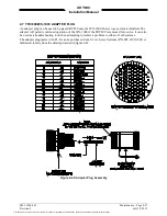
Remove antenna from airframe, along with the special adapter plate and o-ring. See Figure 4-43.
4.
Disconnect each of the three antenna cables (Sum port is blue with TNC connector, Bit port is center
BNC connector and the Delta port is red with a TNC Connector).
4.8.6 Antenna Replacement
NOTES
1.
A doubler plate (not supplied) is required to reinforce the aircraft
skin.
2.
When mounting the antenna install the O-ring in the groove on the
bottom of the antenna. If the O-ring is already installed and held on
with tape, remove tape before installing antenna (refer to SL-206).
The document reference is online, please check the correspondence between the online documentation and the printed version.

