background image

SKY899 

Installation Manual 


009-11900-001 


Appendix B - Page B-1 

Revision F 


July 18, 2013 

Appendix  B 


Environmental Qualification Form 

This appendix includes the environmental qualification forms required for the SKY899 system. Forms 
included are for the TRC899, NY156 & NY164 antennas, and WX-1000/SKY497 display. 

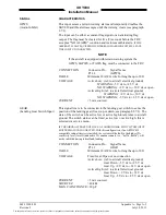
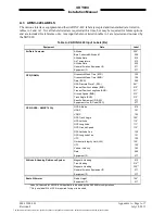
B.1  SKY899 ENVIRONMENTAL QUALIFICATION FORM (FIXED WING: DO-160D) 

(Reference Document 016-11933-001) & (016-11957-001) 
 
MODEL: TRC899  TSO NO: 

TSO-C147, Class A. and TSO-C118 

PART NO:  805-11900-001 

APPLICABLE SPEC NO:  RTCA/DO-197A 

MANUFACTURER: 

L-3 Communications Avionics Systems, Inc. 

ADDRESS: 

5353 52nd St. SE, Grand Rapids, MI 49512-9704 

Revision and change number of DO-160:  DO-160D (RF Susceptibility to Chg 1)   


DO-160C (Vibration, section 8.5) 


CONDITION


SECTION-

PARAGRAPH


TEST CATEGORY


Temperature and Altitude 
Low Temperature 
High Temperature 
Loss of Cooling 
Altitude 
Decompression 
Overpressure 

4.0 

4.5.1 

4.5.2 & 4.5.3 

4.5.4 
4.6.1 
4.6.2 
4.6.3 

Equipment tested to Category F2 

-55

°

 Celsius 

+70

°

 Celsius 

Category X-No test performed 

55,000 ft. MSL 
Not Applicable 
Not Applicable 

Temperature Variation 

5.0 

Equipment tested to Category B 

Humidity 

6.0 

Equipment tested to Category A 

Operational Shock and Crash Safety 

7.0 

Equipment tested to Category B 

Vibration 

8.0 

Equipment tested to Category S, aircraft 
zone 2 using vibration test curves B and M 
for fixed wings 
Critical frequencies for sinusoidal test, 
curve M: 

X axis:  14.83 Hz  @  3.18 g 
 

22.35 Hz  @  4.72 g 

Y axis:  47.25 Hz  @  4.23 g 
 

73.45 Hz  @16.03 g 

Z axis:  44.44 Hz  @  6.25 g 
 

73.45 Hz  @  7.87 g 

No changes in critical frequencies were  

observed in all three major test axes. 

The document reference is online, please check the correspondence between the online documentation and the printed version.

Summary of Contents for 805-11900-001

Page 1: ...5 11900 001 Installation Manual This manual contains installation instructions and recommended flightline maintenance information for the SKY899 Traffic Alert Advisory System This information is supplemented and kept current by revisions service letters and service bulletins The document reference is online please check the correspondence between the online documentation and the printed version ...

Page 2: ...briefly and include the manual part number the paragraph figure table number and the page number Send your comments to L 3 Communications Avionics Systems Attn Technical Publications 5353 52 nd Street S E Grand Rapids MI USA 49512 9704 Telephone 800 453 0288 or 616 949 6600 Fax 616 977 6898 WARNING INFORMATION SUBJECT TO EXPORT CONTROL LAWS These commodities are controlled under the Export Adminis...

Page 3: ... Aerospace will begin servicing units on April 27 2015 Units received by L 3 Avionics Systems from April 27 and later will be sent to Extant Aerospace Please use the following address for shipping and receiving invoices and address labeling Extant Aerospace 1615 W NASA Blvd Melbourne FL 32901 For technical support or troubleshooting help call Telephone 888 327 7994 US Canada International 321 473 ...

Page 4: ...The document reference is online please check the correspondence between the online documentation and the printed version ...

Page 5: ...The document reference is online please check the correspondence between the online documentation and the printed version ...

Page 6: ...The document reference is online please check the correspondence between the online documentation and the printed version ...

Page 7: ...DIX C INSTALLATION CHECKOUT USING THE TCAS 201 RAMP TEST SET This appendix contains instructions for doing post installation and return to service checkout of the SKY899 using the IFR Systems TCAS 201 Ramp Test Set with TCAS I firmware APPENDIX D INSTALLATION CHECKOUT USING THE TIC T 49C FLIGHTLINE TESTER This appendix contains instructions for doing post installation and return to service checkou...

Page 8: ...ape from O Ring gasket on NY156 NY164 Antenna s SL 209 Service Letter As of June 1 2006 all new TRC899 s will ship with software 1 7 or later SL 219 Service Letter stating that L 3 Communications Avionics Systems grants permission to use our STC and installation data for installations and approvals of SKY899 SKY899A SL 233 Service Letter for SKY899 SKY899A installations using alternate displays re...

Page 9: ...n F Highlights Revision F is a republication This republication completely replaces the existing book It incorporates the basic manual and all previous changes New and revised material has been added including Pg 1 1 Remove step 8 with ADS B statements Pg 1 2 Remove s ADS B statements from functional description Pg 1 14 Remove s ADS B statements from Surveillance range within the specifications pa...

Page 10: ...llation 2 1 INTRODUCTION 2 1 2 2 UNPACKING INSPECTION AND STORAGE 2 2 2 3 ANTENNA LOCATION 2 2 2 4 TRC LOCATION 2 3 2 5 DISPLAY LOCATION 2 4 2 6 CABLE REQUIREMENTS AND FABRICATION 2 17 2 6 1 Antenna Cables 2 18 2 6 2 Audio Output Cable 2 18 2 6 3 Data Cable 2 19 2 6 4 Heading Input Cable 2 19 2 6 5 Power Cable 2 20 2 6 6 Suppression Bus Cable 2 20 2 6 7 WX 1000 SKY497 Display and WX 1000 Processor...

Page 11: ...21 SUPPRESSION BUS I O 2 30 2 22 SYSTEM CONFIGURATION MODULE 2 31 2 23 WX 1000 SKY497 DISPLAY OPTIONAL 2 32 2 24 WX 1000 PROCESSOR OPTIONAL 2 32 2 24 1 SKYWATCH Stormscope Mode Switch 2 33 2 24 2 External Overide Switch 2 33 2 25 ANTENNA INSTALLATION 2 33 2 26 TRC MOUNTING TRAY INSTALLATION 2 35 2 27 TRC INSTALLATION 2 36 2 28 MOUNTING THE WX 1000 SKY497 DISPLAY 2 38 2 28 1 Panel Cutout 2 38 2 28 ...

Page 12: ...5 TROUBLESHOOTING 4 24 4 6 ERROR MESSAGES 4 25 4 7 TRC899 WX 1000 ADAPTER PLUG 4 27 4 8 RETURN TO SERVICE 4 28 4 8 1 TRC899 P N 805 11900 001 Removal 4 28 4 8 2 TRC899 P N 805 11900 001 Replacement 4 28 4 8 3 Display Removal 4 29 4 8 4 Display Replacement 4 29 4 8 5 Antenna Removal 4 29 4 8 6 Antenna Replacement 4 30 4 9 DISPOSITION OF FAILED ITEMS 4 31 Appendix A SKY899 Interface Signal Cable Cha...

Page 13: ... E 1 Appendix F Installation Checkout Using an Alternate Display F 1 INTRODUCTION F 1 F 2 CONTROLS F 1 F 3 CHECKOUT PROCEDURE F 2 F 3 1 System Setup F 3 F 3 2 Calibration F 8 F 3 3 Information Menu Data Monitors F 9 F 3 4 Self Test F 9 F 3 5 Ground Test F 10 Appendix G SKYWATCH HP SKY899 Permission to use STC SA01552CH D for Raytheon C90 Permission to use STC SA01552CH D for Raytheon C90 G 1 Appen...

Page 14: ...Inside Backshell 2 31 Figure 2 10 Antenna Mounting Holes 2 34 Figure 2 11 Directional Antenna Installation 2 34 Figure 2 12 Mounting Holes for Standard Mounting Tray P N 805 10870 001 2 35 Figure 2 13 Mounting Holes for Ruggedized Mounting Tray P N 805 10870 003 2 36 Figure 2 14 TRC899 Installation 2 37 Figure 2 15 Instrument Panel Cutout and Mounting Holes 2 38 Figure 2 16 Display Installation 2 ...

Page 15: ...r 4 16 Figure 4 34 Mag Heading Data Monitor 4 16 Figure 4 35 Radio Altitude Data Monitor 4 16 Figure 4 36 Antenna Calibration Menu 4 17 Figure 4 37 Ground Test Menu 4 18 Figure 4 38 Ground Test in Progress 4 18 Figure 4 39 Configuration Management Menu 4 19 Figure 4 40 Compact Flash Insertion Instructions 4 20 Figure 4 41 Service Menu Tree Sheet 1 of 3 4 21 Figure 4 42 Adapter Plug Assembly 4 27 F...

Page 16: ...l Antenna Attached H 1 Figure H 2 IFR 6000 Test Set Basic Controls H 2 Figure H 3 TCAS Setup Screen H 2 Figure H 4 Test Position Setup H 3 Figure H 5 TCAS Screen ATCRBS H 4 Figure H 6 SKY899 Start up Screen H 5 Figure H 7 Standby Screen H 5 The document reference is online please check the correspondence between the online documentation and the printed version ...

Page 17: ...lay Cable Vendors 1 23 Table 2 1 Soft Key Connection Options 2 30 Table 2 2 WX 1000 SKY497 Display Connection 2 32 Table 2 3 WX 1000 Processor Connection 2 32 Table 3 1 List of Illustrations 3 1 Table 4 1 Alternate Display Drivers 4 12 Table 4 2 Fault Isolation 4 24 Table 4 3 Installation Related Error Messages 4 25 Table 4 4 Informational Error Messages 4 26 Table 4 5 List of Return to Service Ch...

Page 18: ...ation Manual Page xii 009 11900 001 July 18 2013 Revision F This page intentionally left blank The document reference is online please check the correspondence between the online documentation and the printed version ...

Page 19: ... Having both displays connected to the soft key inputs could result in conflicting input commands to the SKY899 and the WX 1000 processor 3 For a list of compatible alternate displays refer to Service Memo 114 For additional assistance contact Field Service Engineering at 1 800 453 0288 or 1 616 949 6600 4 The SKY899 does not track intruder aircraft approaching at a closure rate greater than 1200 ...

Page 20: ... SKYWATCH HP are listed below Category SKY497 SKY899 Active ATCRBS Surveillance Range 11 nmi surveillance range 35 nmi surveillance range Active ATCRBS Interrogation Power Low power interrogations High power interrogations Active ATCRBS Interference Limiting No interference limiting TCAS I interference limiting Closure Rate 900 kn closure rate 1200 kn closure rate Antenna Configurations Single dir...

Page 21: ...e responding aircraft s range altitude and closure rates are computed to plot traffic location and predict collision threats The effective active range is approximately 35 nmi The SKY899 does not transmit ADS B information in order to transmit your aircraft position you must have a mode S transponder capable of ADS B interrogations Figure 1 1 shows the typical vertical display modes and traffic zo...

Page 22: ... Page 1 4 General Information 009 11900 001 July 18 2013 Revision F Figure 1 2 SKY899 System Block Diagram The document reference is online please check the correspondence between the online documentation and the printed version ...

Page 23: ...fferent versions refer to para 1 4 2 and 1 4 3 1 3 1 TRC899 Transmitter Receiver Computer P N 805 11900 001 The TRC is mounted in a mounting tray supplied with the installation kit see Table 1 2 The standard tray Figure 1 3 will meet the requirements for fixed wing aircraft A ruggedized version of the tray Figure 1 4 is required for installations in a high vibration environment To meet different s...

Page 24: ...70 001 Right Angle 90 Degree Backshell 1 613 10043 001 I O Connector 100 Position Female Mil C 38999 Series III 1 605 10251 001 Includes 22D Crimp Terminals Spare Terminals for I O Connector 10 M39029 56 348 Power Connector 3 Position Straight Plug 1 MS3126F12 3S Includes 16 Crimp Terminals Spare Terminals for Power Connector M39029 32 247 4 607 10018 001 System Configuration Module Assembly 1 814...

Page 25: ...0 001 General Information Page 1 7 Revision F July 18 2013 Figure 1 3 Standard TRC Mounting Tray P N 805 10870 001 The document reference is online please check the correspondence between the online documentation and the printed version ...

Page 26: ...1900 001 July 18 2013 Revision F Figure 1 4 Ruggedized TRC Mounting Tray P N 805 10870 003 Figure 1 5 P1 Connector Dimensions Reference Only The document reference is online please check the correspondence between the online documentation and the printed version ...

Page 27: ...aircraft installation dependent information via the service menu The system configuration is read from the module during turn on The module is included in the installation kit and is designed to be installed inside the backshell of connector P1 see Figure 1 7 System Configuration Module Figure 1 7 System Configuration Module The document reference is online please check the correspondence between ...

Page 28: ... to TSO C113 If the equipment tag on the back of the unit see Figure 1 8 does not identify SKYWATCH and TSO C113 return the display to the factory for modification To schedule workload and ensure a quick turn around a return authorization will be required Call Customer Service 1 800 453 0288 or 1 616 949 6600 for details Figure 1 8 WX 1000 SKY497 Display Equipment Tag NOTE The original Stormscope ...

Page 29: ...al 009 11900 001 General Information Page 1 11 Revision F July 18 2013 Figure 1 9 WX 1000 SKY497 Display The document reference is online please check the correspondence between the online documentation and the printed version ...

Page 30: ... 1 10 depicts the antenna dimensions Table 1 4 Airframe Installation Kits MANUFACTURER AIRFRAME INSTALLATION KIT PART NUMBER AEROSPATIALE ATR 42 817 10009 001 BAE RAYTHEON HAWKER 400 600 700 800 and 1000 817 10009 004 BEECH BEECHJET KING AIR 90 100 200 300 and 350 BARON 33 35 36 55 58 BE 99 1300 1900C D 817 10009 001 817 10009 002 CANADAIR CHALLENGER 600 and 601 817 10009 005 CESSNA CITATION III V...

Page 31: ...0 cm Radius 1 817 10009 003 800 10066 004 Special Adapter Plate 80 Inch 203 2 cm Radius 1 817 10009 004 800 10066 003 Special Adapter Plate 32 Inch 81 3 cm Radius 1 817 10009 005 800 10066 005 Special Adapter Plate 47 Inch 119 4 cm Radius 1 817 10009 006 No Adapter Plate 100 10022 001 101 10027 001 Screw 10 32 x 1 PPH SS MS51958 67 Stop Nut 10 32 MS21044C3 4 4 Hardware supplied with all kits Figur...

Page 32: ...lative altitude tracking range 10 000 ft maximum DISPLAY RANGES Horizontal display ranges Display Dependent WX 1000 SKY497 Display defaults at 2 6 15 nmi Additional driver selectable ranges between 2 and 24 nmi are available Relative altitude display ranges 2 700 ft normal mode 9 000 ft to 2 700 ft above mode look up 2 700 ft to 9 000 ft below mode look down 9 900 ft to 9 900 ft unrestricted RANGE...

Page 33: ...05 10890 001 NY164 White Paint 805 10890 002 NY164 Black Paint SIZE Height 1 30 inches 3 30 cm Max Width 6 25 inches 15 87 cm Max Length 11 12 inches 28 24 cm Max WEIGHT 2 3 lb 1 04 kg SPEED Rated to 600 knots 0 9 Mach 25 000 feet FREQUENCY 1030 1090 MHz TSO CATEGORY C118 ENVIRONMENTAL CATEGORY DO 160C For further details refer to Appendix B Environmental Qualification Form FINISH Gloss white or b...

Page 34: ...n 102 For Collins ProLine 4 transponder interface corrects label 350 used by the maintenance computer Corrects valid altitude limits for Collins ALT 50 and ALT 55 and King KRA405 and KRA10 10A altimeter interface Corrects intruder heading for Meggit Magic Display System ARINC 429 heading interface 1 6 1 07 Refer to Service Bulletin 116 Corrects the use of the antenna calibration factor when using ...

Page 35: ...ed if Terrain Warning System GPWS EGPWS or TAWS is installed Only if Alternate Display requires it see display manufacturer s instructions Required and may be provided by the display e g WX 1000 SKY497 display OFF BRT switch 1 7 EQUIPMENT REQUIRED BUT NOT SUPPLIED Antenna Cables The installer will supply all antenna cables and connectors The directional antenna requires three cable assemblies sum ...

Page 36: ...3 5 19 68 4 5 Frequency 1030 MHz Loss 2 5 dB at 1030 MHz includes all cables and connectors VSWR 1 5 1 at 1030 MHz Electronic Cable Specialists 1 800 327 9473 414 421 5300 FAX 414 421 5301 Part Number Attenuation dB 100 ft 1 0 gHz Weight lb per 100 ft Maximum Length ft Minimum Bend Radius in 352001 12 2 2 7 15 0 81 311601 8 7 5 5 26 1 15 311201 5 56 8 5 41 1 59 310801 3 63 16 1 63 2 26 PIC Wire an...

Page 37: ...t Angle 311601 CTS922 CTR922 CBS922 CBR922 311201 CTS122 CTR122 CBS122 CBR122 310801 CTS022 CTR022 CBS022 CBR022 352001 CTS3522 CTR3522 CBS3522 CBR3522 PIC Wire and Cable 1 800 742 3191 262 246 0500 FAX 262 246 0450 Cable Part Number TNC Straight TNC Right Angle BNC Straight BNC Right Angle S33141 190308 190309 190312 190313 S55122 190608 190609 190612 190613 S22089 190408 190409 190412 190413 Ant...

Page 38: ... M22520 5 61 ECS Cable 311201 Die M22520 5 21 ECS Cable 310801 Die 190318 PIC Cable S33141 Die 190418 PIC Cable S22089 Die 190618 PIC Cable S55122 P1 Interconnect Crimping Tool M22520 2 01 Positioner M22520 2 07 Insertion MS27495 A22M Removal MS27495 R22M P8 Power Crimping Tool M22520 1 01 Positioner M22520 1 02 Insertion MS24256A16 Removal MS24356R16 P101 Display Crimping Tool M22520 2 01 Positio...

Page 39: ...al Mechanical Technologies EMTEQ 1 888 679 6170 262 679 6170 FAX 262 679 6175 WX 5 6 84 lb 100 ft 3N6607 7 5 lb 100 ft TZGYR 6 84 lb 100 ft WX 1000 SYNCHRO WM25807 7 2 lb 100 ft CFLX C07243T 01 Lamps external annunciators External annunciators are required when using an alternate display that is not capable of displaying above below and unrestricted vertical modes Lamp outputs are switched to grou...

Page 40: ...ice A standard 9 pin serial cable is required Surface Preparation Alodine No 1001 required for installation of the antenna Switches Alternate Display ON OFF A separate ON OFF switch may be required Any general purpose SPDT toggle switch 1 2 A 28 V dc may be used OPR STB Depending upon display capabilities a separate momentary switch may be required to toggle between operate and standby modes RANGE...

Page 41: ...U S COMPANY DISPLAY CABLE P N WEIGHT LB PER 100 FT Dallas Avionics 1 800 527 2581 214 320 9776 FAX 214 320 1057 WX 3 10 5 Electronic Cable Specialists 1 800 327 9473 414 421 5300 FAX 414 421 5301 3N6715 16 A E Petsche 817 461 9473 FAX 817 277 2887 TZDIS 13 1 PIC Wire and Cable 1 800 742 3191 262 246 0500 FAX 262 246 0450 WM25815 14 5 EDMO Distributors 1 800 235 3300 509 535 8280 FAX 1 800 828 0623...

Page 42: ...l Page 1 24 General Information 009 11900 001 July 18 2013 Revision F This page intentionally left blank The document reference is online please check the correspondence between the online documentation and the printed version ...

Page 43: ...l Tolerances unless otherwise indicated Angles are 5 Degrees 00 Two Place Decimals are 01 000 Three Place Decimals are 005 2 2 UNPACKING INSPECTION AND STORAGE CAUTION The display and TRC are sensitive to electrostatic discharge ESD and may be damaged if not handled correctly Do not remove protective covers from electrical connectors during unpacking Touching an exposed connector may cause electro...

Page 44: ...given to relocating other antennas to obtain the furthest forward location for the directional antenna The antenna should be mounted on the aircraft with at least 20 dB isolation about 30 inches 76 2 cm from other L band frequency antennas and 24 inches 61 0 cm from other antennas or obstructions The ground plane should be as large as possible a 30 inch 76 2 cm ground plane diameter is recommended...

Page 45: ...ble and clearly visible to the pilot If using an alternate display device refer to manufacturer instructions for location In selecting a location for WX 1000 SKY497 display consider the following Magnetic Effect Where possible to avoid it the display should not be mounted within 3 inches 8 cm of an electric turn and bank indicator as the magnetic effect of the turn and bank motor may affect the di...

Page 46: ...anual Page 2 4 Installation 009 11900 001 July 18 2013 Revision F This page intentionally left blank The document reference is online please check the correspondence between the online documentation and the printed version ...

Page 47: ...01 Installation Page 2 5 2 6 blank Revision F July 18 2013 Figure 2 2 Interconnect Wiring Without WX 1000 sheet 1 of 2 The document reference is online please check the correspondence between the online documentation and the printed version ...

Page 48: ...This page intentionally left blank The document reference is online please check the correspondence between the online documentation and the printed version ...

Page 49: ...01 Installation Page 2 7 blank 2 8 Revision F July 18 2013 Figure 2 2 Interconnect Wiring Without WX 1000 sheet 2 of 2 The document reference is online please check the correspondence between the online documentation and the printed version ...

Page 50: ...This page intentionally left blank The document reference is online please check the correspondence between the online documentation and the printed version ...

Page 51: ...001 Installation Page 2 9 blank 2 10 Revision F July 18 2013 Figure 2 3 Interconnect Wiring with WX 1000 Sheet 1 of 2 The document reference is online please check the correspondence between the online documentation and the printed version ...

Page 52: ...This page intentionally left blank The document reference is online please check the correspondence between the online documentation and the printed version ...

Page 53: ...01 Installation Page 2 11 blank 2 12 Revision F July 18 2013 Figure 2 3 Interconnect Wiring with WX 1000 Sheet 2 of 2 The document reference is online please check the correspondence between the online documentation and the printed version ...

Page 54: ...This page intentionally left blank The document reference is online please check the correspondence between the online documentation and the printed version ...

Page 55: ...stallation Page 2 13 blank 2 14 Revision F July 18 2013 Figure 2 4 Interconnect Wiring with Alternate Display Sheet 1 of 2 The document reference is online please check the correspondence between the online documentation and the printed version ...

Page 56: ...This page intentionally left blank The document reference is online please check the correspondence between the online documentation and the printed version ...

Page 57: ...stallation Page 2 15 blank 2 16 Revision F July 18 2013 Figure 2 4 Interconnect Wiring with Alternate Display Sheet 2 of 2 The document reference is online please check the correspondence between the online documentation and the printed version ...

Page 58: ...This page intentionally left blank The document reference is online please check the correspondence between the online documentation and the printed version ...

Page 59: ...aragraph ARINC 429 All cable routing should be kept as short and direct as possible Avoid routing the cables too close to aircraft control cables Avoid routing cable near the ADF comm radio or transponder antenna cables allow at least a 12 inch 30 5 cm separation Avoid routing cable near power sources e g 400 Hz generators trim motors etc and near power for fluorescent lighting Use pressurized bul...

Page 60: ...a TNC connector at each end Affix a blue marking band on each connector At the TRC the sum port J9 is identified with blue marking Bit Probe Port The Bit Probe port is the center antenna connector Fabricate the probe cable with a BNC connector at each end Difference Delta Port The Difference Delta port is the rear antenna connector It is marked with a red band Fabricate the difference antenna cabl...

Page 61: ...ties The synchro cable consists of the following refer to Figure 2 5 1 Twisted Shielded Jacketed Triad 24 AWG Colors White Blue Orange Shield Tin Plated Copper Braid 90 min Jacket FEP 007 in min White 2 Twisted Shielded Jacketed Pair 24 AWG Colors White Blue Shield Tin Plated Copper Braid 90 min Jacket FEP 007 in min Blue 3 Same as Item 2 except Orange jacket 4 Aluminized Mylar Wrap 5 34 AWG braid...

Page 62: ...WX 1000 Stormscope Weather Mapping System is installed the same cable is used to connect the TRC to a WX 1000 processor Refer to Figure 2 2 without WX 1000 processor or Figure 2 3 with WX 1000 processor for interconnect wiring information Pin out information relating to the WX 1000 display and processor is also provided in Table 2 2 and Table 2 3 For alternate display device cable see ARINC 429 da...

Page 63: ... positions use the insertion and extraction tools listed in paragraph 1 7 under sub title Connector Installation Some of the differences TRC899 TRC497 7 ARINC 429 RX channels 2 ARINC 429 RX channels 3 ARINC 429 TX channels 1 ARINC 429 TX channel System Configuration Module Individual configuration pins Heading valid 1 input pin active low or high Heading valid 2 input pins active low or high Analo...

Page 64: ...affic is still annunciated CAUTION Do not connect a switch to the extended audio switch input EXT_AUDIO_SW P1 32 unless the TRC899 has Mod D and Software Version 1 8 or higher Any SPST switch 1 2 A 28 V dc can be connected to P1 32 see notes on Figure 2 2 2 3 or 2 4 Extended Audio Callout Switch connection EXT_AUDIO_SW P1 32 2 7 2 GPWS Audio inhibit The audio inhibit input will sense a terrain war...

Page 65: ...conds after takeoff and switch back to standby 24 seconds after landing A squat switch would also prevent the pilot from placing SKYWATCH HP in standby i e pressing the STB button while the aircraft is in flight 2 8 ALTERNATE DISPLAY Alternate display s are connected to the ARINC 429 TX1 output channel Each alternate display will show the information consistent with the capabilities of that partic...

Page 66: ...same speed 12 5 or 100 kHz 2 The data rate for RX channels 3 and 4 must be set to the same speed 12 5 or 100 kHz 3 The data rate for channel 5 is independent of the other receivers Channel 5 can be set to 12 5 or 100 kHz ARINC 429 General Sensor Input connections A429RX1_A P1 54 A429RX1_B P1 55 A429RX2_A P1 62 A429RX2_B P1 63 A429RX3_A P1 64 A429RX3_B P1 65 A429RX4_A P1 73 A429RX4_B P1 74 A429RX5_...

Page 67: ...ut is delayed when a terrain warning system flag alarm is detected and remains delayed until the warning clears Connect this output to an unmuted audio panel input Two outputs 150 ohm and 600 ohm can supply up to 40 mW to the audio distribution system Volume level is set via the Service Menu Audio output connections AUDIO_H P1 89 600 Ohm AUDIO_L P1 90 150 Ohm AUDIO_C P1 91 Audio Common 2 11 BAROME...

Page 68: ...efer to paragraph 2 9 1 for ARINC 429 general sensor input information In order to use ADS B in the future when it is standardized SKYWATCH HP requires a GPS input that is GAMA or ARINC 743A compliant 2 13 HEADING INPUT Heading can be provided by synchro XYZ or ARINC 429 attitude heading and reference system depending on the configuration settings Heading source will be selected during system setu...

Page 69: ... Refer to Appendix A for electrical characteristics Lamp connections LP1OUT P1 66 ABV LP2OUT P1 85 BLW Depending on the vertical display mode selected the appropriate annunciator s will light If in normal mode neither lamp will light if in above mode the ABV lamp will light if in below mode the BLW lamp will light and when unrestricted vertical mode is selected both lamps will light See Figure 2 7...

Page 70: ...to display a TA i e adjust sensitivity levels and when to mute aural announcements to minimize pilot distraction i e suppress SKY899 audio Without the benefit of radio altitude ground speed or the landing gear position are used to determine sensitivity level and audio suppression NOTE The radio altimeter must provide full range output between 0 and 2500 feet Not all altimeters provide this full ra...

Page 71: ... kHz Refer to paragraph 2 9 1 for ARINC 429 general sensor input information 2 19 SERIAL DATA The TRC has one RS 232 debug port J7 terminal device for service menu access The TRC has an auxiliary RS 232 and RS 422 data bus designated for future use do not connect at this time Debug port connection DIAG_GND P7 5 DIAG_RX P7 2 DIAG_TX P7 3 CTS P7 7 RTS P7 8 Auxiliary RS 232 connection future use RS23...

Page 72: ...ft key inputs Table 2 1 Soft Key Connection Options SIGNAL NAME FUNCTION WX 1000 SKY497 DISPLAY ALTERNATE DISPLAY S SFTKEY1_IN P1 18 MSG Connect Do not Connect SFTKEY2_IN P1 19 TEST ALT NRM ABV BLW UNR Connect Connect Momentary Switch external switch or alternate display open collector output Label external switch TEST ALT TEST or ALT depending on alternate display capabilities SFTKEY3_IN P1 20 RA...

Page 73: ...anged without having to re configure the TRC When powered up the configuration information is sent to the TRC via the bi directional serial data bus SDA NOTE The system configuration module must be located inside the backshell of connector P1 and wire tied to the bundle of wires Reference Figure 2 9 System Configuration Module connections System Configuration Module TRC899 Red VCC to P1 2 3 3V Bla...

Page 74: ...LOW WHITE P1 20 SFTKEY4_IN 24 YELLOW BLUE P1 21 SW2 required if WX 1000 Processor installed see figure 2 2 2 24 WX 1000 PROCESSOR OPTIONAL The SKYWATCH HP can be interfaced to the Stormscope weather mapping system The connections are listed in Table 2 3 Table 2 3 WX 1000 Processor Connection WIRE COLOR FUNCTION WX 1000 PROCESSOR SUB CABLE WIRE TRC899 SHIELD P301 5 PWRSWHI P301 21 GREEN WHITE SW2 P...

Page 75: ...display PWSWHI and PWSWLO signals from the WX 1000 processor to the TRC ON OFF control lines The maintenance switch cable routing and length are not critical to system operation The switch can be located in the avionics bay near the WX 1000 processor TRC ON OFF power control switch connection ON OFF P1 4 ON OFF_RET P1 5 2 25 ANTENNA INSTALLATION The following paragraphs provide installation detail...

Page 76: ...groove on the bottom of the antenna 2 For pressurized aircraft use a sealant that meets the requirements of SAE AMS S 8802 such as Flamemaster CS3204 class B For non pressurized aircraft use a non corrosive sealant that meets the physical requirements of MIL A 46146 such as General Electric RTV162 Figure 2 10 Antenna Mounting Holes Figure 2 11 Directional Antenna Installation The document referenc...

Page 77: ...mounting tray P N 805 10870 003 required for installations in a high vibration environment must be channel mounted 1 Position tray at the installation location 2 Determine centers for mounting holes and drill for required fasteners See Figure 2 12 standard tray or Figure 2 13 ruggedized tray 3 Secure tray in place using suitable 8 32 channel mount or 6 32 flat mount hardware Figure 2 12 Mounting H...

Page 78: ... tray by tightening the self locking hold down knobs 3 Connect the three antenna inputs to the connectors on the front panel 4 Connect the Sum port antenna connector P9 a TNC connector identified with a blue band to connector J9 identified with blue marking 5 Connect the Probe Bit port antenna connector P10 a BNC connector identified with a black band to connector J10 6 Connect the Difference Delt...

Page 79: ...Manual 009 11900 001 Installation Page 2 37 Revision F July 18 2013 Figure 2 14 TRC899 Installation The document reference is online please check the correspondence between the online documentation and the printed version ...

Page 80: ... front or rear The following paragraphs describe the installation procedure 2 28 1 Panel Cutout Refer to Figure 2 15 for the panel cutout and mounting hole dimensions Drill and punch the required holes The instrument panel cutout is a standard 3ATI Figure 2 15 Instrument Panel Cutout and Mounting Holes The document reference is online please check the correspondence between the online documentatio...

Page 81: ...vironments Figure 2 16 Display Installation Use Rivnuts or a mooring clamp to secure the display to the instrument panel NOTE 1 The mooring clamp is not furnished with the display 2 A mooring clamp P N 78 8060 5856 2 can be ordered when the order for the display is placed 3 A 3ATI mooring clamp is also available from MSP Incorporated R R 4 Box 383A Nashville Indiana 47448 Tel 812 988 6623 or FAX 8...

Page 82: ...anual Page 2 40 Installation 009 11900 001 July 18 2013 Revision F This page intentionally left blank The document reference is online please check the correspondence between the online documentation and the printed version ...

Page 83: ... 2 All test equipment used in completing these tests shall be calibrated in accordance with the manufacturer s recommendations 3 This section provides checkout information for the SKY899 using the WX 1000 Display If using an alternate display use Appendix F for installation checkout 4 Checkout of the WX 1000 processor should be done in accordance with the procedures detailed in the WX 1000 Install...

Page 84: ...a Traffic Advisory i e a solid circle at nm and Other Traffic i e open diamond at 4 5 nm Both targets will be displayed in level flight at own aircraft altitude i e 00 displayed above the traffic symbol If the indications given in the following procedure except for the Flightline Tester are not obtained refer to the troubleshooting procedures in Chapter 4 If indications given for the Flightline Te...

Page 85: ...ge Calibration will be done during system setup verification and operation Figure 3 3 Standby Screen 3 3 1 System Setup The system configuration can be done using the service menu or it can be downloaded with a previously saved configuration using the Compact Flash Card Both setup procedures are described below and assume familiarity with service menu operation see chapter 4 for operation informat...

Page 86: ...d at a comfortable level then select exit to return to setup menu 5 From the Setup menu select ARINC 429 ports and manually configure each receiver channel Refer to paragraph 4 4 1 4 NOTES 1 It is possible for multiple data inputs barometric altimeter radio altimeter magnetic heading and GPS navigation from one source to be received on one channel e g ARINC 429 superbus Multiple data inputs will b...

Page 87: ...eturn to Service Menu e The Save or Revert menu will appear upon exiting setup menu Select Save Changes to keep current configuration Selecting Revert to Old Settings will cause system to exit the service menu without saving changes 7 To verify changes made to the configuration module turn the SKY899 OFF and then enter the Service Menu see paragraph 4 4 and repeat Step 6 8 Perform system setup ver...

Page 88: ...h altitude and heading sensor Verify data monitors show the correct input changes i e sensing of these signals b If the information is not correct the sensor has failed to communicate with the TRC Check operation of the sensor and connections between the TRC and sensor c Select exit until you return to the Service Menu 4 From the Service Menu select Ground Test see paragraph 4 4 4 5 From the Groun...

Page 89: ... to sub step f If the Flightline Tester AC Converter Power Supply is to be utilized proceed to sub step d d Connect the AC Converter Power Supply cable connector to the chassis external connector e Connect the AC Converter Power Supply input power cable connector to one of the following AC sources 115 Vac 60 Hz 115 Vac 400 Hz f Set the Flightline Tester POWER switches to the ON position g Verify t...

Page 90: ...path distortion see step 1 3 During these tests the SKY899 may detect and display other active targets 4 To obtain a better line of sight it may be necessary to elevate the patch antenna d Set the TT391 POWER switch to the OFF Repeat procedure from each test point Step 15 can be done from the last test point NOTE To prevent SKYWATCH HP from tracking the movement of the test set it is necessary to ...

Page 91: ...are cleared from the aircraft s instruments 2 Turn SKY899 ON The display should show a start up screen similar to one shown in Figure 3 2 3 After approximately thirty seconds observe the STANDBY screen and then press the TEST button soft key 2 4 The display should present a screen similar to that shown in Figure 3 5 Figure 3 5 Self Test Screen 5 If the SKY899 passes the self test the system will r...

Page 92: ...be connected to P1 89 AUDIO_H 2 150 ohm audio systems should be connected to P1 90 AUDIO_L 3 Audio common is connected to P1 91 AUDIO_C NOTE Audio output from the TRC is transformer isolated 7 If SKY899 fails the self test a The SKY899 Failed screen with an error message indicating the type of failure will be displayed b The voice message SKYWATCH SYSTEM TEST FAILED will be enunciated over the coc...

Page 93: ...s Removal of components is on condition of failure 4 3 PERIODIC MAINTENANCE At regular inspection intervals do the periodic maintenance procedures of paragraph 4 3 1 thru 4 3 3 4 3 1 WX 1000 SKY497 Display 1 Check that indicator cable is properly mated and secured 2 Check to ensure unit is properly placed and secured to the instrument panel CAUTION Do not use cleaning solvents on the viewing face ...

Page 94: ... at the end of this section figure 4 41 When interfaced to an alternate display the service menu functions are accessed via an RS 232 terminal device figure 4 1 using a terminal emulation program see appendix E for operating instructions To access the service menu from the terminal emulation program type the menu command and then type the corresponding prefix for each selection e g 1 2 x etc Servi...

Page 95: ...e Menu screens are shown for documentation purposes only Each system may be configured differently and live data will correspond to the sensors installed in a particular aircraft 4 4 1 Setup The setup menu configures the SKY899 system to your specific installation Setup covers the aircraft type antenna system audio level ARINC 429 ports and avionics equipment In the setup menu the current choice i...

Page 96: ...ices Figure 4 5 Aircraft Type Menu 4 4 1 2 Antenna System The SKY899 allows you to install the antenna on top or bottom of aircraft and can use the NY156 TCAS I installation or NY164 antenna Only one antenna location can be selected when choosing an antenna location the other location will automatically be set to None WARNING Verify displayed antenna position matches antenna location on the aircra...

Page 97: ...Audio Level The audio level menu allows you to set and test the audio level output Audio level range is 0 to 40 mW into 600 Ohm load indicated by percentage 0 100 Audio level can be adjusted up or down in 5 increments Selecting test will cause the traffic traffic aural message to be annunciated over the aircraft audio system The Audio Level menu provides the following choices Figure 4 8 Audio Leve...

Page 98: ...hen it checks for label 371 general aviation equipment ID If the equipment can not be identified then the receiver channel will be set to the default of NoType and NoSpeed Autodetect will not work for multiple data inputs i e ARINC 429 superbus Selecting ARINC 429 ports from the Setup menu will cause the ARINC 429 Receivers menu to appear Figure 4 9 ARINC 429 Receivers Menu NOTES 1 The data rate f...

Page 99: ...aft select Browse All Avionics from the avionics equipment menu Browse function will sequentially step through the setup of all avionics equipment interfaces After completing Browse All Avionics selections corrections can be made by selecting the individual items from the Equipment menu The Avionics Equipment menu provides the following choices Figure 4 13 Avionics Equipment Menu If ARINC 429 equi...

Page 100: ...Menu The Avionics Equipment sub menus are as follows The GPS Nav menu provides the following choices Figure 4 15 GPS Nav Menu The Heading menu provides the following choices Figure 4 16 Heading Menu The document reference is online please check the correspondence between the online documentation and the printed version ...

Page 101: ...Radio Altimeter menu lists the known altimeter manufacturers and models that are compatible with SKY899 see appendix A for signal characteristics For digital interfaces select ARINC 429 label 164 required Select Arinc 552 or Arinc 552A for units that comply with these characteristics All other choices are DC analog interfaces highlight your manufacturer model and press SEL Selecting a DC analog ra...

Page 102: ...d Line Menu The Landing Gear menu provides the following choices Figure 4 21 Landing Gear Menu The Weight On Wheels squat switch menu provides the following choices Figure 4 22 Weight On Wheels Menu The document reference is online please check the correspondence between the online documentation and the printed version ...

Page 103: ...ypical display drivers to be used with the WX 1000 SKY497 display and available for use with alternate displays Sextant 1501 1502 displays and Forestry Service drivers should be selected only for those specific installations If the system has more than one display the current range altitude mode and the number of intruders displayed may be different between displays The display drivers determine w...

Page 104: ...e version system error log and real time sensor data data monitor If you have problems with the SKY899 record the software version and the error messages then verify the Data Monitor screens match the aircraft wiring Have this information available when contacting Field Service Engineering The field service engineer must have adequate information to diagnose a problem Select Information from the S...

Page 105: ... error messages Figure 4 27 System Log Menu The System Log displays the results in the following format hhhhhh mm where Error code hhhhhh mm Run time in hours and minutes when error occurred The total elapsed run time is displayed beside the title in the upper middle portion of the screen Sys Log hhhhhh mm With an error highlighted pressing SEL will cause the textual description to appear undernea...

Page 106: ...n change has been saved You can change the sensor source save it and have the data monitor reflect the change without cycling power to the system This will help in troubleshooting installation problems The ARINC 429 Receivers Data Monitor screen shows the configuration of the ARINC 429 receivers If any parity errors were detected the error count per channel will be shown A large increasing number ...

Page 107: ...his could be used as a means for evaluating interference For example if an active transponder lowers the value by more than 5 dBm system performance has been degraded by 5 dBm Figure 4 30 Antenna Calibration Data Monitor The Barometric Altitude Data Monitor screen shows the barometric encoded altitude in gray code and feet and connector P1 pin assignments for the data inputs Figure 4 31 Barometric...

Page 108: ...nitor screen shows data read from the heading source i e heading flag flag configuration Figure 4 34 Mag Heading Data Monitor The Rad Alt Data Monitor screen shows data read from the radio altimeter e g source altitude in feet warning flag and flag configuration Figure 4 35 Radio Altitude Data Monitor The document reference is online please check the correspondence between the online documentation...

Page 109: ...not configured will have an invalid BIT phase message NOTE If the TRC has never been calibrated the current calibration value will be displayed as Invalid The Calibration menu provides the following choices Figure 4 36 Antenna Calibration Menu The calibration value 000 359 is derived from a variety of measurements Specific values are meaningless however in a failed TRC a varying spread may indicat...

Page 110: ...t screen displays the following Figure 4 37 Ground Test Menu Selecting Perform Ground Test initializes the ground test software and displays the following Figure 4 38 Ground Test in Progress The buttons perform the following operations in this mode EXIT causes the system to return to the Information Menu Soft key 2 toggles the system through the above ABV normal NRM below BLW and unrestricted UNR ...

Page 111: ...ation This backup copy can be used to later restore system configuration or download system configuration to other installations i e OEM installation of same equipment model s during aircraft production Retrieve from CF Retrieve from compact flash allows you to copy a previously saved system configuration from a compact flash to your system Restore Factory Defaults Restore factory defaults changes...

Page 112: ...ile the TRC899 is powered on may result in damage to the card 2 At the TRC899 see figure 4 40 open the memory card door and insert compact flash into J12 connector Be sure to align the arrow on the compact flash card with the arrow above the memory card door Figure 4 40 Compact Flash Insertion Instructions The document reference is online please check the correspondence between the online document...

Page 113: ...l 009 11900 001 Maintenance Page 4 21 Revision F July 18 2013 Figure 4 41 Service Menu Tree Sheet 1 of 3 The document reference is online please check the correspondence between the online documentation and the printed version ...

Page 114: ...l Page 4 22 Maintenance 009 11900 001 July 18 2013 Revision F Figure 4 41 Service Menu Tree Sheet 2 of 3 The document reference is online please check the correspondence between the online documentation and the printed version ...

Page 115: ...l 009 11900 001 Maintenance Page 4 23 Revision F July 18 2013 Figure 4 41 Service Menu Tree Sheet 3 of 3 The document reference is online please check the correspondence between the online documentation and the printed version ...

Page 116: ...play Replace Display Display is distorted Check for interference from aircraft systems Incorrect response to buttons soft keys Check soft key wiring inside display cable and WX 1000 processor cable if installed SKY899 will not enter service menu a If using an WX 1000 SKY497 display check soft key wiring b If using an alternate display service menu must be accessed with an RS 232 terminal device Ap...

Page 117: ... TRC Alternate Display Output P1 42 A429TX1 A P1 43 A429TX1 B 4 6 ERROR MESSAGES The 20 most recent errors detected by the system are saved in the System Log see paragraph 4 4 2 2 For your convenience in Table 4 3 we have listed the error messages that have been associated with SKY899 installations Where appropriate procedures that may assist in resolving installation problems are provided When a ...

Page 118: ...le a Verify GPS source is it turned on and locked onto satellites b Using the service menu verify configuration speed and equipment type is set correctly c Check ARINC 429 wiring associated with GPS MSG Heading Input Error Degraded message appears on WX 1000 display No heading input being received ARINC 429 or synchro compass Degraded operation will cause targets to disappear from the screen when ...

Page 119: ...WX 1000 if the TRC899 is removed for service It can also be used as a troubleshooting tool when attempting to isolate a problem to either or both systems The adapter plug mates with P1 It can be purchased from L 3 Avionics Systems P N 805 11910 001 or fabricated locally from the details provided in figure 4 42 Figure 4 42 Adapter Plug Assembly The document reference is online please check the corr...

Page 120: ...robe Bit port antenna connector P10 a BNC connector identified with a black band from connector J10 c Disconnect the Difference Delta port antenna connector P11 a TNC connector identified with a red band from connector J11 identified with red marking 4 Loosen the self locking hold down knobs and remove the retainer cups from over the TRC J hooks 5 Remove TRC from the mounting tray 4 8 2 TRC899 P N...

Page 121: ...nt panel from the front or from the rear determine how it was originally installed in order to reinstall WX 1000 SKY497 Display 1 At rear of display connect cable connector P101 25 pin to display connector J101 2 Install the display into the instrument panel and use the four screws to secure the display Alternate Display 1 At rear of display connect the cable to display connector 2 Install the dis...

Page 122: ...l adapter plate and o ring using four 10 32 screws See Figure 4 43 5 Seal antenna to the airframe see sealant types below For pressurized aircraft use a sealant that meets the requirements of SAE AMS S 8802 such as Flamemaster CS3204 class B For non pressurized aircraft use a non corrosive sealant that meets the physical requirements of MIL A 46146 such as General Electric RTV162 Figure 4 43 Direc...

Page 123: ...are installed on the exposed terminals of cable connectors on the display TRC and antenna 2 The display and TRC contain electrostatic discharge sensitive ESDS parts and must be wrapped in static protective materials 3 Wrap with bubble pack Secure bubble pack with reinforced tape 4 Place assembly in a cardboard box 5 Wrap any accessories in tissue and place in the box Fill spaces with bubble pack 6...

Page 124: ...anual Page 4 32 Maintenance 009 11900 001 July 18 2013 Revision F This page intentionally left blank The document reference is online please check the correspondence between the online documentation and the printed version ...

Page 125: ...er Input inputs coming from an airdata computer or encoding altimeter see paragraph 2 11 These 11 lines may be connected in parallel with the aircraft transponder If the aircraft is equipped with selectable altitude encoders connect the altitude inputs so that SKY899 is always connected to the selected encoder Reference ARINC 572 1 NOTES 1 Only one altimeter input source gray code or ARINC 429 not...

Page 126: ...ed 2 5 dB VSWR 1 5 1 without antenna connected Refer to paragraph 2 6 1 Impedance 50 Ω Antenna Top Directional BIT PROBE Port Black J10 CONNECTION Connector Signal Name J10 BNC BIT CABLE Cable and connector attenuation must not exceed 6 dB VSWR 1 5 1 without antenna connected Refer to paragraph 2 6 1 Impedance 50 Ω Antenna Top Directional DIFFERENCE DELTA Port Red J11 CONNECTION Connector Signal N...

Page 127: ... TRC can accept Radio Altimeter input from ARINC 429 or DC analog source The Barometric Altitude can be ARINC 429 or Gilham Code The Heading can be ARINC 429 or Synchro XYZ Select only one source for each aircraft input 3 If 429 barometric altitude is used it should be from the same source that is interfaced with the transponder or it must be at least as accurate as that source i e 125 ft 4 Receiv...

Page 128: ...no hardware flow control Baud Rate 19 200 Data Bits 8 Parity None Stop Bits 1 Flow Control Xon Xoff CONNECTION Connector Pin Signal Name J7 2 DIAG_RX J7 3 DIAG_TX J7 5 DIAG_GND J7 7 CTS J7 8 RTS Extended Audio Switch Required to enable the ViP Extended Audio Callout feature An extended audio callout switch is required when interfacing to the extended audio switch input P1 32 of the TRC899 Units wi...

Page 129: ... GEAR This signal line is to be connected to the landing gear switch to sense the Landing Gear Switch Input position of the landing gear fixed up or down see paragraph 2 7 2 The state of the switch can be active low or active high in reference to aircraft ground The switch status can be fixed active low or active high this is selected via service menu IF THE AIRCRAFT DOES NOT HAVE A LANDING GEAR S...

Page 130: ...n 320 Hz Max 480 Hz VOLTAGE Min 3 V ac rms Max 35 V ac rms INPUT IMPEDANCE 50 kΩ CONNECTION Connector Pin Signal Name P1 49 HEADING_H P1 50 HEADING_C CABLE See paragraph 2 6 4 Heading Valid Indicates that the heading source is providing valid heading information The status of the heading valid signal can be none active low or active high and must be selected during system setup via the service men...

Page 131: ...ll light if in above mode the ABV lamp will light if in below mode then the BLW lamp will light and when unrestricted vertical mode is selected both lamps will light CONNECTION Connector Pin Signal Name P1 66 LP1OUT ABV P1 85 LP2OUT BLW CABLE Minimum 22 AWG wire for lengths up to 30 ft VOLTAGE ON 0 V dc or Ground OFF Maximum 32 V dc or open CURRENT Maximum current 300 mA ON OFF Power This input tu...

Page 132: ...OLTAGE 18 to 32 V dc 2 0 Amps Maximum Radio Altimeter Analog A radio altimeter enables ground intruder filtering optimizes TA sensitivity levels and makes it possible to inhibit audio below 400 AGL Some analog radio altimeters utilize a discrete valid invalid signal line to indicate radio altitude validity while others set the analog data input line to a high out of range value for invalid altitud...

Page 133: ...istic 552 0 to 2500 ft 0 to 26 0944 V 0 to 500 ft 20 mV ft 500 to 2500 ft 10 Ln 2 178 x ft 500 ARINC Characteristic 552A 0 to 2500 ft 0 to 26 1741 V 20 to 480 ft 20 mV ft 0 4 V 480 to 2500 ft 10 Ln 2 178 x ft 20 500 Bonzer Mark 10X 40 to 2500 ft 0 4 to 25 V 40 to 2500 ft 10 mV ft Collins ALT 50 0 to 2000 ft 0 to 16 4 V 18 0 5 V Offscale 20 to 500 ft 20 mV ft 0 4 V 500 to 2000 ft 3 mV ft 10 4 V Col...

Page 134: ...anufacturer instructions concerning these connections Required soft key connections will depend upon the alternate display capabilities e g some displays control operation mode internally and ranges externally while others handle ranges internally and operation modes externally When installing multiple alternate displays soft keys inputs may require several displays being connected to the same inp...

Page 135: ...ddition the SKY899 receives suppression signals from all other devices on the suppression bus e g transponder DME Reference ARINC 735 2 and DO 197A CAUTION The aircraft transponder must have suppression circuitry to ensure that SKYWATCH HP does not paint itself as a target e g TA CONNECTION Connector Pin Signal Name P1 93 SUPBUS CABLE Any size low capacitance shielded cable may be used VOLTAGE 18 ...

Page 136: ... Processor if installed and output to the display Signal levels as specified in RS 422 specification CONNECTION Connector Pin Signal Name P1 35 VIDEO_IN From Processor P1 36 VIDEO_IN From Processor P1 16 VIDEO_OUT To Display P1 17 VIDEO_OUT To Display CABLE See paragraph 2 6 7 VOLTAGE 0 5 V dc CURRENT 100 mA FREQUENCY 15 MHz LOAD Z 1 kΩ WX 1000 SKY497 Display Power supply to WX 1000 SKY497 display...

Page 137: ...ION Connector Pin Signal Name P1 1 5 V P1 3 15 V P1 32 DI02 P1 77 RS422_TXA P1 78 RS422_TXB P1 79 RS422_RXA P1 80 RS422_RXB P1 86 RS232_TX2 P1 87 RS232_RX2 P1 88 RX232_GND2 P1 83 A429RX7_A P1 84 A429RX7_B P1 81 A429RX8_A P1 82 A429RX8_B P1 44 A429TX2_A P1 45 A429TX2_B P1 52 A429TX3_A P1 53 A429TX3_B The document reference is online please check the correspondence between the online documentation a...

Page 138: ...Manual Page A 14 Appendix A 009 11900 001 July 18 2013 Revision F This page intentionally left blank The document reference is online please check the correspondence between the online documentation and the printed version ...

Page 139: ... 11900 001 Appendix A Page A 15 A 16 blank Revision F July 18 2013 Figure A 1 I O Connector P1 Pin Assignments The document reference is online please check the correspondence between the online documentation and the printed version ...

Page 140: ...This page intentionally left blank The document reference is online please check the correspondence between the online documentation and the printed version ...

Page 141: ... GPS Discrete Word 1 DSC 261 Present Position Latitude BNR 310 Present Position Longitude BNR 311 Ground Speed BNR 312 Track Angle BNR 313 Specific Equipment ID DSC 371 Equipment Hex ID Code DSC 377 GPS GNSS ARINC 743A GPS Altitude 076 HDOP 101 VDOP 102 GPS Track Angle 103 GPS Latitude 110 GPS Longitude 111 GPS Ground Speed 112 GPS Latitude Fine 120 GPS Longitude Fine 121 UTC 125 Horizontal Integr...

Page 142: ...itude Select Limits 015 DITS Control 016 Intruder Range 130 Intruder Altitude 131 Intruder Bearing 132 Own A C Altitude 203 Vertical RA 270 Transponder Control 274 Own A C Heading 320 Fault Summary 350 RTS Request To Send 357 ETX End of Transmission 357 GA Equipment Ident 371 Equipment Identifier 377 The document reference is online please check the correspondence between the online documentation ...

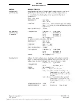
Page 143: ...PH TEST CATEGORY Temperature and Altitude Low Temperature High Temperature Loss of Cooling Altitude Decompression Overpressure 4 0 4 5 1 4 5 2 4 5 3 4 5 4 4 6 1 4 6 2 4 6 3 Equipment tested to Category F2 55 Celsius 70 Celsius Category X No test performed 55 000 ft MSL Not Applicable Not Applicable Temperature Variation 5 0 Equipment tested to Category B Humidity 6 0 Equipment tested to Category A...

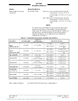
Page 144: ...nt identified as Category X No test performed Fungus Resistance 13 0 Equipment identified as Category X No test performed Salt Spray 14 0 Equipment identified as Category X No test performed Magnetic Effect 15 0 Equipment to meet Class Z Power Input 16 0 Equipment tested to Category B Voltage Spike 17 0 Equipment tested to Category A Audio Frequency Susceptibility 18 0 Equipment tested to Category...

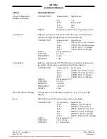
Page 145: ... and Crash Vibration 8 0 Equipment tested to Category C L M and Y Explosion 9 0 Category X No test performed Waterproofness 10 0 Equipment tested to Category S Fluids Susceptibility 11 0 Equipment tested to Category F Sand and Dust 12 0 Equipment tested to Category D Fungus 13 0 Equipment tested to Category F Salt Spray 14 0 Equipment tested to Category S Magnetic Effect 15 0 Category X No test pe...

Page 146: ...titude 4 6 1 55 000 Feet MSL Temperature Variation 5 0 Tested to Category C Humidity 6 0 Tested to Category A Operational Shock and Crash Safety 7 0 Operational Shock 7 2 6 g s Peak Crash Safety 7 3 15 g s all axes Vibration 8 0 Tested to Categories NBM Instrument Panel Mount Without Vibration Isolators Explosion Proofness 9 0 Category X No test required Waterproofness 10 0 Category X No test requ...

Page 147: ...y Emission 21 0 Tested to Category A Lightning Induced Transient Susceptibility 22 0 Category X No test required Lightning Direct Effects 23 0 Category X No test required Icing 24 0 Category X No test required Other Tests X Ray Radiation Other Tests U V Radiation Other Tests Thermal Shock The document reference is online please check the correspondence between the online documentation and the prin...

Page 148: ...Manual Page B 6 Appendix B 009 11900 001 July 18 2013 Revision F This page intentionally left blank The document reference is online please check the correspondence between the online documentation and the printed version ...

Page 149: ... operation of the TCAS 201 ramp test set 2 All test equipment used in completing these tests shall be calibrated in accordance with the manufacturer s recommendations 3 When the SKY899 is interfaced to an alternate display reference Appendix F while performing this checkout procedure C 2 CONTROLS All operating controls are located on the front of the WX 1000 SKY497 display Figure C 1 shows the loc...

Page 150: ... 9 4 dB LOSS 1 3 dB SETUP 2 RANGE MAX 35 NM was 20 NM for Sky497 RANGE MIN 0 NM ALT MAX 60 000 ft ALT MIN 0 ft SCENARIO TEST RANGE 5 0 NM RANGE RATE 200 kt ALT 51 000 ft ALT RATE 0 FPM REPLY TEST RANGE 5 0 NM ALTITUDE 50 500 ft REPLY 100 2 Make sure the aircraft s transponder is in the STBY mode and the DME is turned OFF Verify all avionics equipment interfaced with the SKY899 i e GPS ADC AHRS syn...

Page 151: ... SKY899 OFF and then enter the Service Menu see paragraph 4 4 by holding the left two buttons soft keys 1 and 2 depressed as the system is turned ON 6 From the Service Menu calibrate the TRC to the directional antenna see paragraph 3 3 2 and 4 4 3 7 Cycle power to the SKY899 and verify the standby screen appears after approximately 30 seconds Press OPR soft key 4 and verify the MSG label does not ...

Page 152: ...hrough the altitude display modes Soft key 2 is labeled to indicate the current mode Press Soft key 2 to toggle between normal NRM below BLW above ABV and unrestricted UNR 17 Select the NRM normal mode 18 Position the aircraft with the nose aligned on any 90 degree heading Avoid areas within 250 ft of obstructions e g hangers large aircraft control towers etc where there is a potential for multipa...

Page 153: ...t to the antenna connector c At the TCAS 201 test set press the SCEN key d Initiate the SCENARIO TEST by pressing the ANTENNA push button switch or the RUN STOP key e Verify that the display shows an other traffic symbol open diamond at the 12 o clock position 30 degrees approximately 5 0 nm and in level flight The traffic symbol should be at an altitude of 500 ft above own aircraft i e 05 and mov...

Page 154: ...Manual Page C 6 Appendix C 009 11900 001 July 18 2013 Revision F This page intentionally left blank The document reference is online please check the correspondence between the online documentation and the printed version ...

Page 155: ...ration of the T 49C Flightline Tester 2 All test equipment used in completing these tests shall be calibrated in accordance with the manufacturer s recommendations 3 When the SKY899 is interfaced to an alternate display reference Appendix F while performing this checkout procedure D 2 CONTROLS All operating controls are located on the front of the WX 1000 SKY497 display Figure D 1 shows the locati...

Page 156: ... scenario is controlled by the microprocessor This altitude like the distance is varied so that the simulated intruder converges on the aircraft s position 1 Make sure the aircraft s transponder is in the STBY mode and the DME is turned OFF Verify all avionics equipment interfaced with the SKY899 i e GPS ADC AHRS synchro compass encoding altimeter is turned ON and signal condition is valid NOTE Af...

Page 157: ...see paragraph 4 5 2 3 a Change the status of the extended audio switch landing gear squat switch altitude and heading sensors Verify data monitors show the correct input changes i e sensing of these signals b If the information is not correct the sensor has failed to communicate with the TRC Check operation of the sensor and connections between the TRC and sensor c Select exit until you return to ...

Page 158: ...abeled OPR Select NRM mode and 6 nm range by pressing appropriate soft keys c Set the TCAS INTRUDER selector switch to the ATCRBS position and the SCENARIO selector switch to the 0 altitude offset position Press INTERROGATE and when the range on the display decreases to 5 NM press TEST This will freeze the scenario and represent a stationary intruder aircraft 5 NM away at the same altitude as the ...

Page 159: ...NOTE It is necessary to wait a few seconds after moving to let the test target stabilize in position 21 This completes testing with the T 49C reattach top lid of the T 49C 22 If installed TURN ON the radio altimeter 23 This completes the post installation checkout procedure The document reference is online please check the correspondence between the online documentation and the printed version ...

Page 160: ...Manual Page D 6 Appendix D 009 11900 001 July 18 2013 Revision F This page intentionally left blank The document reference is online please check the correspondence between the online documentation and the printed version ...

Page 161: ... Bits 8 Parity None Stop Bits 1 Flow Control Xon Xoff To access the service menu with RS 232 terminal emulation software running type menu Enter The following will appear Service Menu 1 Setup 2 Information 3 Calibration 4 Ground Test 5 Configuration Management x Exit Choice Figure E 1 Service Menu The terminal device Service Menu is similar to the one described in Chapter 4 except for a prefix Typ...

Page 162: ... COMMANDS DESCRIPTIONS or Help The or help command displays a list of available commands or Help Displays the following list fdrec track mbite mxmit head rad discretes bar gps say volume mrep cal ground adsb dump attrib comflash copy del delay dir echo hello help menu ren restart time type ver For Information on any particular command enter the command followed by help i e ident help or abbreviate...

Page 163: ...ace use P N 805 11400 003 or 004 or RGC350 use P N 805 12400 001 or 002 3 This procedure assumes familiarity with the set up and operation of the TT391 Flightline Tester and RS 232 terminal device see Appendix E If using another approved tester refer to the appropriate appendices for test procedure 4 All test equipment used in completing these tests shall be calibrated in accordance with the manuf...

Page 164: ...al Lamps F 3 CHECKOUT PROCEDURE The TT391 Flightline Tester simulates both a ground based secondary surveillance radar SSR and an airborne transponder With the SKY899 set to GROUND TEST i e the barometric altimeter is simulated to 50 000 ft heading simulated to 0 degrees and the radar altimeter simulated to 2 500 ft the TT391 will simulate two targets a Traffic Advisory i e a solid circle at nm an...

Page 165: ...edures have been completed the display may show fail messages If the messages do not go away after system setup and calibration refer to the troubleshooting section in paragraph 4 5 F 3 1 System Setup 1 At the terminal device enter the Service Menu by typing Menu Enter Service Menu 1 Setup 2 Information 3 Calibration 4 Ground Test 5 Configuration Management x Exit Choice NOTE The service menu disp...

Page 166: ... WARNING Verify displayed antenna position matches antenna location on the aircraft top or bottom Failure to do so could give incorrect traffic bearing Antenna System 1 Top Antenna None 2 Bot Antenna None x Back Choice Top Antenna 1 None 2 NY164 Directional 3 NY156 Directional x Back Choice a The Antenna System menu will appear select correct antenna location Top 1 Enter or Bottom 2 Enter b The an...

Page 167: ... the ARINC 429 Receiver Menu 2 The data rate for receive channels 1 and 2 must be set to the same speed 12 5 or 100 kHz The data rate for receive channels 3 and 4 must be set to the same speed 12 5 or 100 kHz The data rate for channel 5 is independent of the other receivers Channel 5 can be set to 12 5 or 100 kHz 3 Autodetect will configure the equipment type and speed of each receiver channel To ...

Page 168: ... GPS 2 Speed 100 kHz x Back Choice Equipment Type 1 NoType 2 BarAlt 3 MagHdg 4 GPS 5 RadAlt x Back Choice Speed 1 12 5 kHz 2 100k Hz Choice b From ARINC 429 Rx Ch menu select Type 1 Enter from the menu c From Equipment Type menu select source equipment from the list 1 5 Enter i e GPS BarAlt etc d If the speed menu appears select the correct speed otherwise proceed to next step e From the ARINC 429...

Page 169: ...OTE As each sub menu appears you must make a selection to continue stepping through the equipment even if the correct selection is already in brackets Selecting Back x Enter will cause it to go backwards to the last sub menu Once you have stepped through all sub menus the equipment menu will reappear b Verify the equipment shown in parentheses under each equipment title matches the wiring interfac...

Page 170: ... standby this does not mean that SKY899 is turned off Calibration 1 Top Antenna Bit Phase 163 84 degs 2 Bottom Antenna Bit Phase Invalid x Back Choice Calibration 1 Top Antenna Bit Phase 163 65 degs 2 Bottom Antenna Bit Phase Invalid x Back Choice RF BITE Calibration Started RF BITE Calibration Passed old 163 93798828 new 163 65234375 RF BITE Calibration Passed old 999 00000000 new 999 00000000 2 ...

Page 171: ... heading sensors Verify data monitors show the correct input changes i e sensing of these signals b If the information is not correct the sensor has failed to communicate with the TRC Check operation of the sensor and connections between the TRC and sensor c Select Back x Enter until you return to the Service Menu F 3 4 Self Test 1 Turn SKY899 OFF and then a Make sure the aircraft s transponder is...

Page 172: ...y mode If external annunciators are connected verify correct operation see Figure F 3 Figure F 3 External Annunciator Operation 6 If OPR annunciator optional is connected verify annunciator works when system is turned ON OPR lamp will not light when in standby or failed mode 7 Select normal NRM mode 8 Position the aircraft with the nose aligned on any 90 degree heading Avoid areas within 250 ft of...

Page 173: ...provide a standard base mounting stud threaded 1 4 20 A typical tripod mount is shown in Figure F 4 c If the internal batteries are being utilized proceed to sub step f If the Flightline Tester AC Converter Power Supply is to be utilized proceed to sub step d d Connect the AC Converter Power Supply cable connector to the chassis external connector e Connect the AC Converter Power Supply input powe...

Page 174: ... direction 30 degrees of the TT391 two targets a Traffic Advisory i e a solid circle at nm and Other Traffic i e open diamond at 4 5 nm Both targets will be displayed in level flight at own aircraft altitude i e 00 displayed above the traffic symbol NOTES 1 If the display reflects a gross error in target bearing check the directional antenna cables at TRC connectors J9 sum port and J11 difference ...

Page 175: ...nt 12 Return the TT391 assemblies to their position in the aluminum carrying case 13 Restart SKY899 by cycling power OFF and then ON 14 Connect an oscilloscope to the suppression bus and verify that the SKY899 suppression pulse 100 µs 5 µs exceeds 15 V dc if less than 15 V dc the suppression bus is overloaded Check all equipment connected to the bus Repair replace the offending device 15 This comp...

Page 176: ...Manual Page F 14 Appendix F 009 11900 001 July 18 2013 Revision F This page intentionally left blank The document reference is online please check the correspondence between the online documentation and the printed version ...

Page 177: ...and owners of the SKYWATCH HP SKY899 Traffic Avoidance System and associated equipment to use this STC and the data associated with it for the sole purpose of installation and approval of the SKYWATCH HP SKY899 System on the aircraft associated with the listed STC Figure G 1 is a copy of the STC cover page For additional assistance or information call L 3 Avionics Systems Customer Service 1 800 45...

Page 178: ...nual Page G 2 Appendix G 009 11900 001 July 18 2013 Revision F Figure G 1 STC SA01552CH D Cover Sheet The document reference is online please check the correspondence between the online documentation and the printed version ...

Page 179: ...familiarity with the set up and operation of the TCAS ramp test set 2 All test equipment used in completing these tests shall be calibrated in accordance with the manufacturer s recommendations 3 A five minute warm up period is required for the IFR 6000 4 When the SKY899 is interfaced to an alternate display reference Appendix F while performing this checkout procedure Figure H 1 IFR 6000 Test Set...

Page 180: ... 6000 flight line tester simulates ATCRBS Mode C or Mode S intruders by manually defining a scenario and can then verify the correct Traffic Advisories and Resolution Advisories have occurred on the SKY899 display Intruding flight patterns are programmed from the IFR 6000 TCAS screen using the following procedure 1 Mount the IFR 6000 directional antenna on the IFR 6000 test set then connect the sh...

Page 181: ...able DIR CABLE LOSS Not Required If test set antenna is detached and connected to the test set using the long RF coaxial cable enter the cable loss value in dB marked on the test set s long RF coaxial cable ANT CABLE 1 ft If test set antenna is detached and connected to the test set using the long RF coaxial cable enter length of long RF coaxial cable ANT CABLE LOSS Variable Entered in dB loss val...

Page 182: ...y be recalled modified and stored under a user named scenario Figure H 5 TCAS Screen ATCRBS 7 Using the NEXT PARAM and PREV PARAM softkeys to select on screen functions set each parameter as shown in Table H 2 Table H 2 TCAS Test Screen Parameters Function Parameter SCENERIO 0 Custom TCAS TYPE TCAS 1 REPLY 100 INTRUDER TYPE ATCRBS RANGE START 6 00 nm RANGE RATE 250 kts ALT START 2000 ft CONVERGE O...

Page 183: ... OFF BRT switch Verify that clockwise rotation increases display brightness Figure H 6 SKY899 Start up Screen After approximately thirty seconds the display will show the STANDBY screen see Figure H 7 NOTE If the TRC has not been calibrated to the directional antenna the display may show a SKY899 FAILED message Calibration will be done during system setup verification and operation Figure H 7 Stan...

Page 184: ...ange Press soft key 3 to toggle the display range between 2 6 and 15 nm 21 Select the 6 nautical mile range 22 Verify that the system toggles through the altitude display modes Soft key 2 is labeled to indicate the current mode Press Soft key 2 to toggle between normal NRM below BLW above ABV and unrestricted UNR 23 Select the NRM normal mode 22 At the IFR 6000 press the RUN TEST softkey to start ...

Reviews: