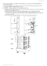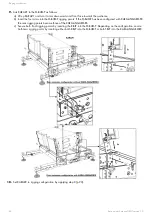
Rigging procedures
Procedure
1.
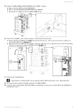
Assemble a KARA-MINIBU/KARA-MINIBUEX rigging structure as follows:
a) Turn the KARA-MINIBU so that the text of the identication plate is readable.
b) Position a rst KARA-MINIBUEX on the laser plate side of the KARA-MINIBU by turning it feet pointing up and
inserting the stud into the slit of the KARA-MINIBU located near the laser plate.
c) Drive 3 bolts into the 3 holes shown the gure below (6 mm hex bit, 13 mm hex key, 7 N.m/63 in.lb f).
d) Repeat the procedure with a second KARA-MINIBUEX on the other side of the KARA-MINIBU.
e) Attach the shackle(s) to the KARA-MINIBU (see
Safety pin removal and insertion
(p.199)) according to the
chosen conguration (see
(p.192)).
If the array is intended to be own in pullback conguration, attach a single shackle to the rear pullback
(p.19)).
2.
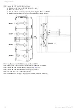
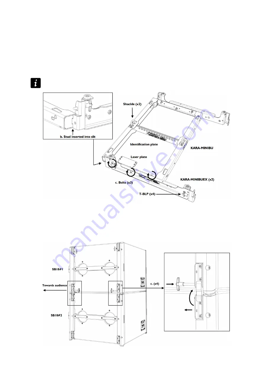
Attach two SB18 (hereafter called SB18#1 and SB18#2) together as follows:
a) Bring two SB18 to the rigging location and remove the dolly boards.
b) Arrange both SB18 in a vertical array, front faces towards audience and logos down. In the following, SB18#1
will designate the top subwoofer and SB18#2 the bottom one.
c) Remove a T-BLP from SB18#2, rotate the link arm up, then re-insert the T-BLP into the SB18#1 link point and the
link arm. Repeat this step until all four arms are secured.
Kara owner's manual (EN) version 1.0
81


