background image


KIVA-SB15

m

_RM_EN_1.1 

w w w . l - a c o u s t i c s . c o m  

13


1.


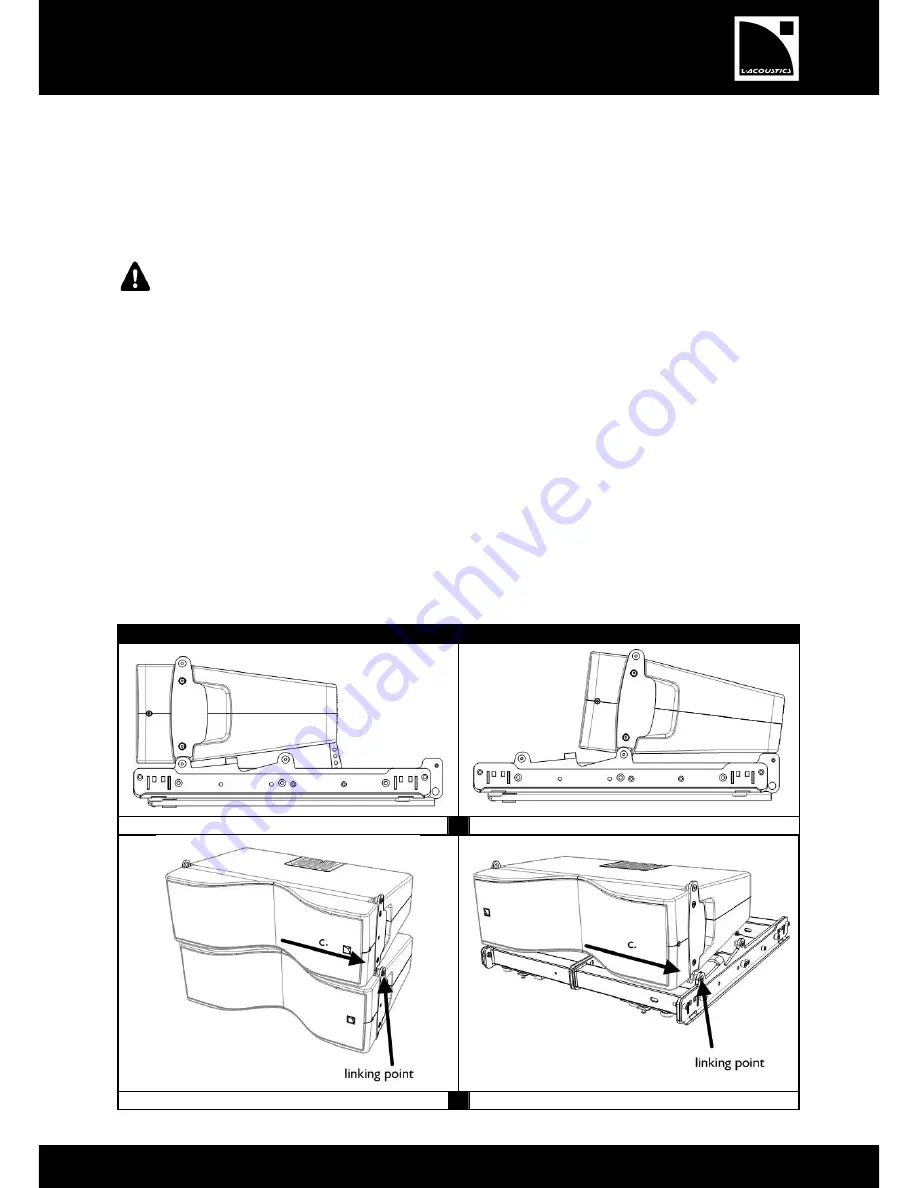
If you are attaching a KIVA enclosure to a  KIBU-SB

, refer to the SOUNDVISION modeling to identify the position 

(rear, front) that corresponds to the targeted site angle. 

2.


Attach the two linking points at the front of the enclosure to the two linking points of the other element (enclosure 

or KIBU-SB). 

a.


Put the enclosure side in contact with the second element. 

b.


Align the enclosure linking points slightly left to the linking points of the other element. 

c.


Slide the enclosure to the right until you hear a clicking sound to secure and lock the system. 


Risk of fall 

After  attaching  an  enclosure,  verify  the  automatic  locking  system  is  engaged:  hold  the  bottom  of  the 

enclosure and shake it side to side. 

3.


Secure  the  angulation  arm  of  the  enclosure  on  the  second  element  using  the  appropriate  hole  for  your 

configuration. 

a.


On the enclosure, pull the spring-loaded pin to release the angulation arm. 

b.


If you are attaching two enclosures 

together

:


i.


Pull the second enclosure spring-loaded pin. 

ii.


Rotate the arm in the second enclosure slot. 

iii.


Select  the  targeted  angle  by  aligning the  top  of  the  arm  with  the  corresponding  notation  on  the  second 

enclosure. 

iv.


Release the spring-loaded pin to its initial position to lock the assembly. 

If you are attaching an enclosure to the KIBU-SB: 

i.


Remove the ball locking pin from the KIBU-SB. 

ii.


Position the angulation arm to position it between the two walls of the KIBU-SB central bar. 

iii.


Select the targeted angle by choosing the appropriate hole on the angulation arm. 
Refer to 

Figure 1 Angulation arm holes

 on page 12. 

iv.


Insert the pin through the holes in KIBU-SB central bar and the enclosure angulation arm. 


PROCEDURE B


Front position. 

1. 

Rear position. 


Attaching KIVA to a second KIVA. 

2. 

Attaching KIVA to KIBU-SB. 

Summary of Contents for KIVA SB15M

Page 1: ...KIVA SYSTEM KIVA SB15m RIGGING MANUAL VERSION 1 1 www l acoustics com...
Page 2: ...the warnings in Mechanical Data section 9 Be cautious when flying a loudspeaker array Always verify that no one is standing underneath the loudspeaker array when it is being raised As the array is be...

Page 3: ...If the product requires repair or for information about the warranty please contact an approved L ACOUSTICS distributor The address of the nearest distributor is available on the L ACOUSTICS web site...

Page 4: ...ded with two SB15MRIG coupling bars equipped with the LOCKTAB locking tab 1 2 Rigging elements KIBU SB Frame for flying KIVA and SB15m enclosures as line elements or independent mixed arrays Provided...

Page 5: ...SB15m_RM_EN_1 1 w w w l a c o u s t i c s c o m 5 KIVA SB15m KIBU SB CLAMP250 SB15MRIG equipped with LOCKTAB Delivered with the SB15m KIET SOUNDVISION Main components involved in the KIVA rigging pro...

Page 6: ...to determine the maximum number of enclosures within an array or to assess the safety of a specific array configuration Mechanical modeling with SOUNDVISION The working load applied to each linking po...

Page 7: ...u s t i c s c o m 7 3 SYSTEM SETUP The KIVA SB15m rigging system relies on the use of KIBU SB as an interface between the two enclosures rigging systems Each side of KIBU SB is compatible with one en...

Page 8: ...op Refer to PROCEDURE B Repeat the previous step until the array is completed Risk of fall Do not climb on a loudspeaker array KIVA SB15m Place one SB15m logo down on the ground If necessary place and...

Page 9: ...up Refer to PROCEDURE A Attach a bow shackle WLL 1 t or a CLAMP250 on the KIBU SB Refer to PROCEDURE B If more than one SB15m is needed raise the array so you can position another SB15m under it Lower...

Page 10: ...re on the ground logo on the left hand side and attach a second enclosure to it Refer to PROCEDURE B Assemble the KIET and the pole adapter and attach the assembly on the KIVA enclosure s Refer to PRO...

Page 11: ...ar by pushing it into place b Pinch the spring tongue and slide the locking tab until it snaps into place When encountering difficulty try to slide the tab from the other side c Verify that the yellow...

Page 12: ...of available angles varies depending of the rigging position front position 0 1 2 rear position 7 5 5 2 5 0 2 5 3 5 4 5 5 5 6 5 7 5 Refer to Figure 1 to choose the hole corresponding to the targeted s...

Page 13: ...the second element using the appropriate hole for your configuration a On the enclosure pull the spring loaded pin to release the angulation arm b If you are attaching two enclosures together i Pull t...

Page 14: ...5m rigging manual VERSION 1 1 KIVA SB15m_RM_EN_1 1 w w w l a c o u s t i c s c o m 14 3 a Releasing the angulation arm Attaching the angulation arm of a KIVA to KIVA 3 b Attaching the angulation arm o...

Page 15: ...umbering on the side of the SB15m KIBU SB hole numbering on the side of the KIVA 2 Attach a shackle or a CLAMP250 to the identified hole by driving the pierced bolt 3 Secure the pierced bolt with the...

Page 16: ...points at the front of the KIET to the two linking points of the enclosure a Place the KIVA enclosure with its logo on the right on a stable horizontal surface b Align the KIET linking points slightly...

Page 17: ...IVA SB15m_RM_EN_1 1 w w w l a c o u s t i c s c o m 17 PROCEDURE D 1 Assembling the KIET and its pole adapter 2 Attaching the KIET and the enclosure 3 Securing the enclosure angulation arm on the KIET...

Page 18: ...tor T20 Torx bit 7 mm hex key 1 Put the KIBU SB with its SB15m side up 2 Undo the four Torx bolts on the laser support plate Use a T20 bit and a 7 mm hex key 3 Place the LAP TEQ on the support plate w...

Page 19: ...C waveguide Nominal impedance 8 RMS power handling 120 W Connectors IN 1 4 point SpeakON LINK 1 4 point SpeakON Rigging components Captive 3 point rigging system Inter enclosure angles 0 1 2 3 4 5 7 5...

Page 20: ...4 point SpeakON LINK 1 4 point SpeakON Rigging components Integrated pole mount socket Coupling bars stored at handle position Dimensions Physical data Weight net 36 kg 79 4 lb Cabinet Baltic birch p...

Reviews: