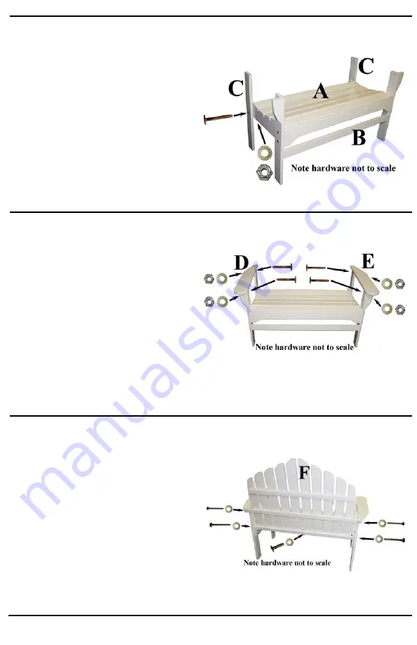
STEP 5
Attach the Back Leg (C) using one 1/4" x
20 x 2" Joint Connector, one 1/4"
washer and one lock nut for each side.
Insert the Joint Connector through the
Back Leg (C) and into the Seat
Assembly (A). Place washer on end of
Joint Connector and finish with lock nut.
Repeat for other side.
Note: Do NOT tighten joint
connectors completely
.
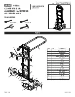
STEP 6
Attach the Right Arm Assembly (D) to
the top of the Front Leg Assembly (B)
using one 1/4" x 20 x 2" Joint
Connector, one washer and one lock nut.
Insert the Joint Connector through the
pre-drilled hole in the Front Leg
Assembly (B), through the pre-drilled
hole in the Right Arm Assembly (D)
before putting on the washer and the
lock nut. Repeat the same procedure for
attaching the Back Leg (C) to the Right
Arm Assembly (D).
Note: Do NOT
tighten joint connectors completely
.
Repeat the above steps to attach the Left
Arm Assembly (E).
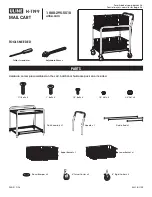
STEP 7
Attach Back Assembly (F) to Seat
Assembly (A) by inserting two 2-1/2”
Lag Bolts with washers through the
holes in Back Legs (C), then tighten into
the Bottom Cleat of the Back Assembly.
Insert two 1-3/4” Lag Bolts with
washers through the predrilled holes in
the arm cleats, then into the predrilled
holes of the middle back cleat of Back
Assembly (F). Insert one 1” Lag Bolt
with washer through the hole in the
center hole of the lower back cleat in
Back Assembly (F) and into the center
seat support.


