background image


0UG61070427 

STEP 11 

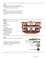
Insert two camlocks into the underside of each Right Wing 

Shelf (E) and Left Wing Shelf (H).  Ensure that the arrow 

on the face of the camlock ’points’ to the hole in the edge of 

the shelf.  Press firmly into place. 


There are two wing shelves for each side of the unit.  They 

can be distinguished by locating the pilot hole on the edge 

of the shelf which will enable you to attach the side panel.  

When the shelf is installed, the pilot hole will face the rear 

of the unit as shown in Step 12. 


STEP 12


Prepare Right Base Wing Shelf (F) and Left Base 

Wing Shelf (I) for installation.  Insert two camlocks 

into the underside of each base wing shelf.  Ensure 

that the arrow on the face of the camlock ’points’ to 

the hole in the edge of the shelf.  Press firmly into 

place. 


The base wing shelves have a cleat across the front 

edge as well as a pilot hole for the attachment of the 

side panel. 


STEP 13 

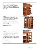
 Attach first Left Wing Shelf (H) to Left Divider 

(A).  Align cam pegs in Left Divider (A) with holes 

in edge of Left Wing Shelf (H).  

Ensure that pilot 

holes in edge of shelf are visible from rear of unit 

as shown.

  Secure first shelf by turning camlocks at 

least 1/2 turn clockwise with Phillips screwdriver 

before placing second shelf. Repeat for other Left 

Wing Shelf (H). 

STEP 14 

Attach Left Base Wing Shelf (I) to Left Divider (A) 

using same technique as in Step 13. Align cam pegs 

in Left Divider (A) with holes in edge of Left Base 

Wing shelf (I

).  Ensure that pilot hole in edge of 

shelf is visible from rear of unit as shown and 

that cleat is toward front of unit.

  Turn camlocks 

at least 1/2 turn clockwise with Phillips screwdriver 

to secure. 


Summary of Contents for MISSION CORNER ENTERTAINMENT STAND

Page 1: ...ank you for purchasing our Mission Corner Entertainment Stand Assembly of this product requires a Phillips screwdriver and a hammer We have found it helpful to have a second person present in at least...

Page 2: ...prevent damage to the finish STEP 3 Identify all parts using diagram at right at list below PARTS Left Divider A Right Divider B Top C 2 Shelf D 2 Right Wing Shelf E Right Base Wing Shelf F Right Side...

Page 3: ...the cam pegs installed in Step 5 point away from the center of the unit Secure center side panel using two 8 screws Do not tighten screws completely in order to more easily install shelves in next few...

Page 4: ...p C Secure using two 8 screws Repeat to Right Divider B Do not tighten screws completely in order to more easily install bottom shelf in next step STEP 9 Repeat Step 8 to attach second Shelf D Ensure...

Page 5: ...he hole in the edge of the shelf Press firmly into place The base wing shelves have a cleat across the front edge as well as a pilot hole for the attachment of the side panel STEP 13 Attach first Left...

Page 6: ...n predrilled holes in Left Side Panel J with pilot holes in edges of Left Wing Shelves H and Left Base Wing Shelf I Secure using one 8 screw for each shelf Tighten all screws securely STEP 17 Repeat u...

Page 7: ...Tighten screws securely STEP 19 Conceal screw holes on side panels using wood plugs Tap plugs gently with a hammer to seat them firmly CARE Dust as needed with a soft cloth Clean with damp cloth and...

Reviews: