
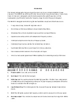
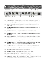


7. INV
low.
This switch reverses the polarity of the low output. When pressed the LED will
light.
8.
Gain Hi output.
This controls the output level of the high band over the range from 0dB to
+6dB.
9. INV
high. This switch reverses the polarity of the high output. When pressed the LED will
light.
10. Xover freq sub woofer
. This controls the crossover frequency of the sub woofer signal
(10Hz-250Hz).
11. Gain sub woofer.
This is used to set the sub woofer output volume.
12. INV sub woofer.
This switch reverses the polarity of the sub output. When pressed the
LED will light.
13. Stereo.
This LED lights up when the crossover is in stereo mode.
14. Mono.
This LED lights up when the crossover is in mono mode.
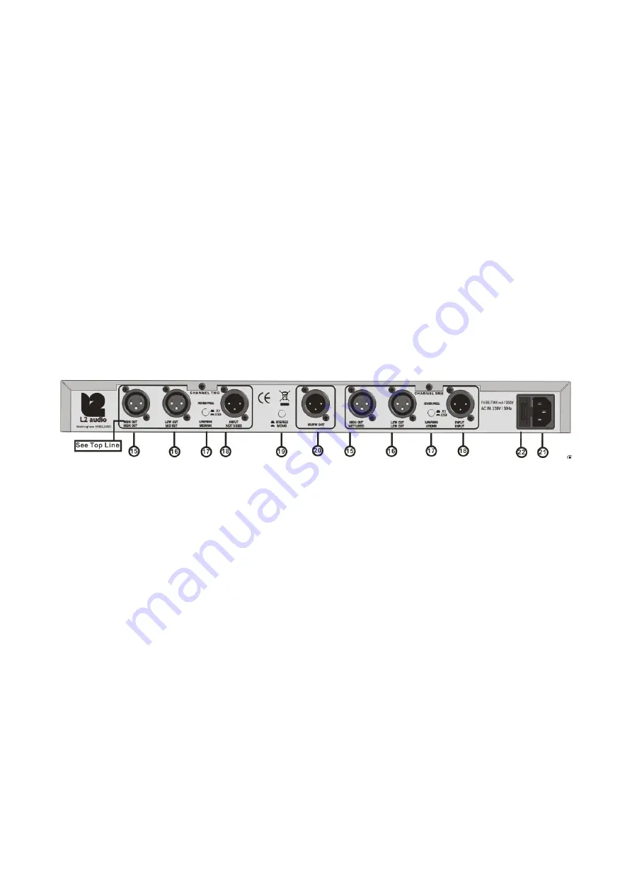
15. High
out.
Balanced XLR connectors. These are outputs for the high band of frequencies.
16. Low
out.
Balanced XLR connectors. These are outputs for the low band of frequencies.
17. Xover
freq.
These are to switch between the control ranges of the crossover frequency
controls on the front panel. The range is either 45 Hz to 960Hz or x10, at 450Hz to 9.6KHz.
When switch is pressed it is indicated on the front panel LED.
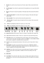
18. Input
connectors. Balanced XLR connectors. These are the units 2 inputs when in stereo
mode.
19. Mode switch.
This switch must be OUT when in stereo mode. PLEASE NOTE. NEVER
ACTIVATE THE MODE AND XOVER FREQ SWITCHES WITH THE UNIT SWITCHED ON! The
mode is indicated on the front panel LED’s (13&14)
20. SubW out.
This is the sub out for the mono sub woofer signal. This signal is constant in
mono or stereo modes and provides an additional means of providing 2 and 3 way
operation.
21. Mains Inlet.
22. Fuse holder.
This is where the mains fuse is housed. If blown, please replace with one of
the same value. If the mains fuse keeps blowing, please refer this appliance to a qualified
personnel.


