background image


Chateau Hoods 


3.  VENTILATION REQUIREMENTS


Requirements of the relevant authorities concerning the discharge of exhaust air must be complied with. 

Never use ducting that is smaller in diameter than the outlet spigot diameter of your cooker hood (see 
Specifications). If you are connecting into a rectangular duct you must ensure that the cross-sectional 
area of this duct is the same or larger than that of the outlet spigot. 

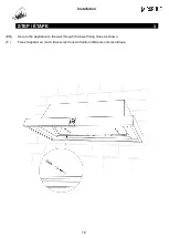
Install ducting before fitting the hood to the wall to prevent debris entering the appliance. We recommend 
the final connection at the cooker hood exhaust spigot is done using semi-rigid ducting for easier fitting 
and  removal  and  to  provide  tolerance  for  any  misalignment  between  the  extractor  spigot  and  fixed 
ductwork. 

Note: We recommend duct holes are 25mm larger than the ducting to enable cables to run alongside 
(such as remote motor or power cables) and to make installing ducting easier. 


4.  FIRE SAFETY


To reduce fire hazards, use metal ducting components. 

Pay particular attention to fire risk when frying. 

Do not flambé under the extractor. 

To minimise the risk of fire, all instructions relating to cleaning the grease filters and removing grease 
deposits must be adhered to.  


5.  COOKER HOOD PERFORMANCE 


The most important influence on the performance of the extractor is the design of the ducting which takes 
the exhaust air from the extractor to the outside. 

Never use ducting that is smaller in diameter than the outlet spigot diameter of your cooker hood (see 
Specifications). If you are connecting into a rectangular duct you must ensure that the cross-sectional 
area of this duct is the same or larger than that of the outlet spigot. 

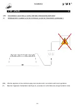
The duct route length should be kept as short as possible with as few bends as possible. 

A route with more than two 90-degree bends can significantly degrade the performance of the extraction 
system. 


   WARNING   

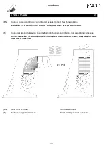
Proper  care  must  be  taken  to  ensure  that  the  negative  pressures  caused  by  high  performance 
extraction systems do not adversely affect the safe operation of certain types of fuel-burning appliances 
(gas, oil or solid fuel), including those installed in the kitchen and possibly also those installed in other 
parts of the house. 
Where such fuel-burning appliances are installed, adequate ventilation MUST be provided in the room 
of installation, located and sized such that the negative pressure in the room created by the extractor 
does not exceed 4Pa. 
In case of doubt, do not operate the extractor and fuel-burning appliance(s) simultaneously and consult 
an appropriate (for the fuel type) expert for advice. 

   WARNING   

The exhaust air must not be discharged into a flue which is used for exhausting fumes from 
appliances supplied with energy other than electricity, e.g. oil or gas-fired central heating boilers, 
gas-fired water heaters, etc. 

Summary of Contents for Chateau 110 60Hz

Page 1: ...z Models Installation Instructions EN 1 Instructions d Installation F 8 La Cornue 14 rue du Bois du Pont Z I les B thunes 95310 Saint Ouen l Aum ne FRANCE Tel 33 0 1 34 48 36 36 Fax 33 0 1 34 64 32 65...

Page 2: ...VENTILATION REQUIREMENTS 6 4 FIRE SAFETY 6 5 COOKER HOOD PERFORMANCE 6 6 DISTANCE FROM THE COOKTOP 7 7 SPECIFICATIONS 7 ILLUSTRATED INSTALLATION GUIDE 13 COOKER HOOD PARTS 14 COOKER HOOD LAYOUT AND F...

Page 3: ...TO REDUCE THE RISK OF A RANGE TOP GREASE FIRE a Never leave surface units unattended at high settings Boilovers cause smoking and greasy spillovers that may ignite Heat oils slowly on low or medium se...

Page 4: ...t electrical technician must perform the electrical installation The extractor is a stationary appliance designed to be cord connected to the electrical supply The extractor must be isolated from the...

Page 5: ...e design of the ducting which takes the exhaust air from the extractor to the outside Never use ducting that is smaller in diameter than the outlet spigot diameter of your cooker hood see Specificatio...

Page 6: ...Filter Quantity Total Power Watts Internal Motor Type Electrical Supply Control System LCH 2000 120V 60Hz Grand Palais 180 Range Hood 2000 134 200mm 6 6 720 W 2 x GX1000 600 CFM Blowers 120 V ac 60 H...

Page 7: ...s means that the equipment cannot be disposed of with other waste that it is the object of a selective collection with a view to recovery reuse or recycling NOW REFER TO THE ILLUSTRATED INSTALLATION G...

Page 8: ...VENTILATION 10 4 S CURIT INCENDIE 10 5 PERFORMANCE DE LA HOTTE 10 6 DISTANCE DE LA TABLE DE CUISSON 11 7 SPECIFICATIONS 11 GUIDE D INSTALLATION ILLUSTR E 13 PI CES DE HOTTE 14 DISPOSITION DE LA HOTTE...

Page 9: ...t aux r glementations en vigueur dans le pays o l appareil est install Cette hotte tant grande et lourde n essayez pas de l installer vous m me Au moins deux personnes sont n cessaires pour installer...

Page 10: ...nce la plus importante sur la performance de l extracteur est la conception de la conduite qui prend l air d chappement de l extracteur l ext rieur N utilisez jamais de conduits d un diam tre inf rieu...

Page 11: ...e Model Largeur mm Poids Kg Sortie Diameter Lumi res LED Quantit de filtre Puissance Electrique Moteur Tension Contr le LCH 2000 120V 60Hz Hotte Grand Palais 180 2000 134 200mm 6 6 720 W 2 x GX1000 60...

Page 12: ...eque l quipement ne peut tre jet avec les autres d chets qu il fait I objet d une collecte s lective en vue de sa valorisation r utilisation ou recyclage REPORTEZ VOUS MAINTENANT AU GUIDE D INSTALLATI...

Page 13: ...Installation 13 ILLUSTRATED INSTALLATION GUIDE GUIDE D INSTALLATION ILLUSTR E...

Page 14: ...anteau de la Hotte 3 Couvre joint 4 LED Lumi re 5 Filtre 6 Bandeau 7 Boutons Electroniques 8 Support Mural PARTS LIST 1 Upper Band 2 Hood Cover 3 Decorative Trim Connector 4 LED Lights 5 Filter 6 Deco...

Page 15: ...sion mm A B C D E F G Grand Palais 180 2000 1600 748 456 760 675 200 Chateau 165 1850 1450 673 418 685 600 200 Chateau 150 1700 1300 598 381 610 525 200 Chatalet 135 1550 1150 523 344 535 450 200 Chat...

Page 16: ...16 STEP TAPE 1 EN Fix the bracket to the wall as shown in the diagram using fixings suitable for your wall F Fixez le support mural au mur comme indiqu sur le sch ma en utilisant des fixations adapt...

Page 17: ...Installation 17 STEP TAPE 2 EN Secure the appliance to the wall bracket as shown F Fixez l appareil au support mural comme indiqu...

Page 18: ...Installation 18 STEP TAPE 3 EN Secure the appliance to the wall through the lower fixing holes as shown F Fixez l appareil au mur travers les trous de fixation inf rieurs comme indiqu...

Page 19: ...RTHER F D BRANCHER L ALIMENTATION LECTRIQUE AVANT DE PROC DER AUTREMENT EN Wire the appliance to the electrical supply via an isolator and in accordance with local regulations F Brancher l appareil l...

Page 20: ...SK OF FIRE USE ONLY METAL DUCTWORK F Connectez les conduits selon votre m thode d chappement pr f r e Voir les options ci dessous AVERTISSEMENT POUR R DUIRE LES RISQUES D INCENDIE UTILISEZ UNIQUEMENT...

Page 21: ...47 before proceeding further F Pour les Frettes sup rieures de plus de 200 mm reportez vous la pages 46 47 avant d aller plus loin EN Secure the Hood Cover to the appliance by following the steps illu...

Page 22: ...Installation 22 STEP TAPE 6 EN Carefully position the Hood Cover over the Decorative Trim F Soigneusement placez le Manteau de la Hotte sur la Bandeau...

Page 23: ...Installation 23 STEP TAPE 6 EN Secure the Hood Cover using the supplied fixings as shown F Fixez le Manteau de la Hotte l aide des vis fournies comme indiqu...

Page 24: ...Installation 24 STEP TAPE 6 EN Secure the Hood Cover using the supplied fixings as shown F Fixez le Manteau de la Hotte l aide des vis fournies comme indiqu...

Page 25: ...Installation 25 STEP TAPE 6 EN Secure the Hood Cover to the wall using the upper fixing holes as shown F Fixez le Manteau de la Hotte au mur en utilisant les trous de fixation sup rieurs comme indiqu...

Page 26: ...Installation 26 STEP TAPE 7 EN Place the Upper Band above the Hood Cover as shown F Placez la Frette au dessus du Manteau de la Hotte comme indiqu...

Page 27: ...APE 7 UPPER BANDS GREATER THAN 200 MM TALL FRETTES SUP RIEURES PLUS GRANDE QUE 200 MM TALL EN Fit the bracket to the Hood Cover and wall as shown F Installez le support sur le Manteau de la Hotte et s...

Page 28: ...Installation 28 STEP TAPE 7 EN Place the Upper Band above the Hood Cover as shown F Placez la Frette au dessus du Manteau de la Hotte comme indiqu...

Page 29: ...as shown Ensure that the deflector nozzle is in line with the vents in the upper band Fit the ducting as shown F Fixez le d flecteur d air au mur comme indiqu Assurez vous que la buse du d flecteur e...

Page 30: ...HOODS REMPLACEMENT DES FILTRES AU CARBONE hottes recyclage EN Carbon filters can be installed by following the 2 steps as shown F Les filtres charbon peuvent tre install s en suivant les 2 tapes indi...

Page 31: ...emote controller with the appliance To register the remote with the appliance Press the light switch on the remote controller several times during the start sequence which lasts for 15 seconds after s...

Page 32: ...ed extensively and filters become dirty LED replacement The long life LED units are not designed for end user replacement In the unlikely event of failure please call La Cornue Caring for HP4 high eff...

Page 33: ...la t l commande sur l appareil Appuyez plusieurs fois sur l interrupteur de la t l commande pendant la s quence de d marrage qui dure 15 secondes apr s la mise sous tension Si l interrupteur principal...

Page 34: ...a hotte est utilis e de mani re intensive et que les filtres devenir sales Remplacement de LED Les unit s DEL longue dur e ne sont pas con ues pour le remplacement de l utilisateur final Dans le cas i...

Page 35: ...he warranty period specified above shall not be extended if faulty parts need to be replaced This warranty shall cease to apply If the operational defect is the result of an unauthorised intervention...

Page 36: ...nce de prolonger la dur e de garantie pr cis e ci dessus La garantie est exclue si le vice de fonctionnement r sulte d une intervention sur le bien effectu e sans authorisation si le fonctionnement d...

Page 37: ...nday through Friday excluding national Holidays by calling 877 LACORNUE CANADA SOFA Galleries 6900 Airport Road Suite 205 Mississauga ONT L4V 1E8 Canada T 855 213 2785 F 905 678 4854 You can find thes...

Page 38: ...38 NOTES NOTER Model No Serial No Installation Date...

Page 39: ...39 NOTES NOTER...

Page 40: ...40 La Cornue 14 rue du Bois du Pont Z I les B thunes 95310 Saint Ouen l Aum ne FRANCE Tel 33 0 1 34 48 36 36 Fax 33 0 1 34 64 32 65 Email a table la cornue com www lacornue com...

Reviews: