background image


16 


THIS PRODUCT.  THIS PRODUCT IS NOT TO BE USED FOR MEDICAL PURPOSES OR FOR PUBLIC 
INFORMATION.  THIS PR

ODUCT IS NOT A TOY.  KEEP OUT OF CHILDREN’S REACH. 

 
This warranty gives you specific legal rights.  You may also have other rights specific to the State.  Some States 
do not allow the exclusion of consequential or incidental damages therefore the above exclusion of limitation 
may not apply to you. 
 

For warranty work, technical support, or information contact: 


La Crosse Technology, Ltd 

2817 Losey Blvd. S. 

La Crosse, WI 54601 

 
Contact Support: 1-608-782-1610 
 
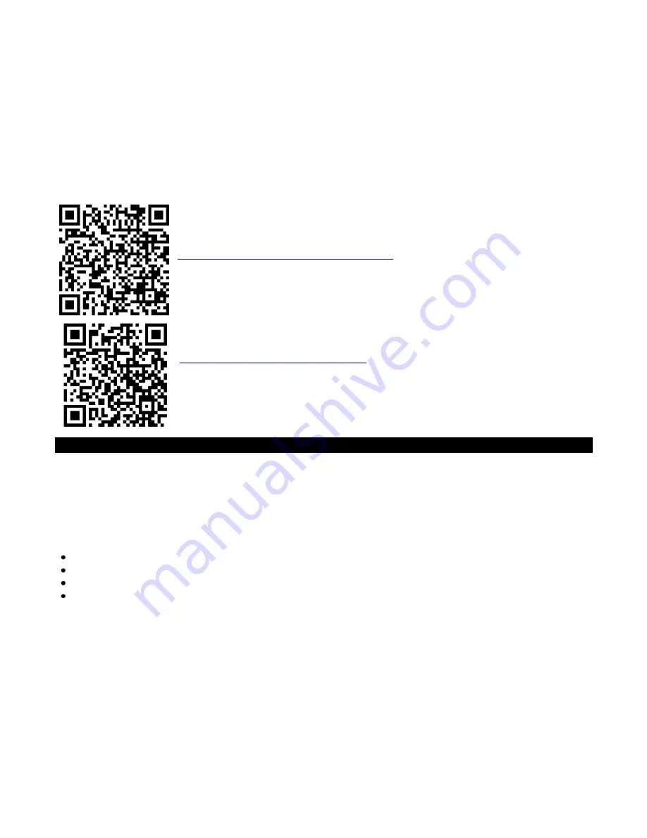
Product Registration:  

www.lacrossetechnology.com/support/register


Online at: 
 

www.lacrossetechnology.com/308-1451  


Protected under U.S. Patents: 
5,978,738 
6,076,044 
6,597,990 


FCC Statement 

 
This equipment has been tested and found to comply with the limits for a Class B digital device, pursuant to part 
15 of the FCC Rules. These limits are designed to provide reasonable protection against harmful interference in 
a residential installation. This equipment generates, uses and can radiate radio frequency energy and, if not 
installed and used in accordance with the instructions, may cause harmful interference to radio communications. 
However, there is no guarantee that interference will not occur in a particular installation. If this equipment does 
cause harmful interference to radio or television reception, which can be determined by turning the equipment 
off and on, the user is encouraged to try to correct the interference by one or more of the following measures:  


Reorient or relocate the receiving antenna. 


Increase the separation between the equipment and receiver.  


Connect the equipment into an outlet on a circuit different from that to which the receiver is connected.  


Consult the dealer or an experienced radio/TV technician for help.  

 
This device must not be co-located or operating in conjunction with any other antenna or transmitter. 

Operation 

is subject to the following two conditions:  
(1) This device may not cause harmful interference, and  
(2) This device must accept any interference received, including interference that may cause undesired 
operation. 


Caution! 


The manufacturer is not responsible for any radio or TV interference caused by unauthorized modifications to 
this equipment. Such modifications could void the user authority to operate the equipment. 
 
All rights reserved. This manual may not be reproduced in any form, even in part, or duplicated or processed 
using electronic, mechanical or chemical process without the written permission of the publisher. 

Summary of Contents for 308-1451

Page 1: ... with 12 hour history forecast icons indoor outdoor temperature and humidity with high and low alarms Five forecast Icons based on temperature air pressure readings suggest what kind of weather to expect Four clothing index icon suggest what to wear This forecast station will never keep you guessing on current or future weather conditions Forecast Station Outdoor Temperature Humidity Transmitter T...

Page 2: ...ooze 9 Frost Alarm 9 Outdoor Temperature Alarms 9 Set Temperature Alarm 1 9 Set Temperature Alarms 2 and 3 9 Temperature Trend Indicators 9 Channel Selection and Auto scroll 10 Pressure Readings 10 Absolute Barometric Pressure Number 10 Pressure Unit of Measurement 10 Pressure History 10 Pressure History Graph 10 Weather Forecast Icons 11 Tendency Indicators 11 Clothing Index 11 MIN MAX Data 12 Lo...

Page 3: ...nsmitter Note The CH switch is set to Channel 1 by default Confirm channel 1 is selected 3 Keep the transmitter 5 10 feet from the forecast station for 15 minutes to establish a good connection 4 Within 3 minutes the forecast station will beep and the outdoor temperature will show If the outdoor temperature does not show after 3 minutes remove power from the transmitter and the forecast station fo...

Page 4: ...catch a signal for up to 10 minutes IMPORTANT When operating on a c power the backlight and USB charge port will turn off while the forecast station searches for the WWVB signal to avoid interference Both features will return after the 2 10 minute search which occurs during the late night or early morning hours Note In case the forecast station is not able to detect the WWVB signal disturbances tr...

Page 5: ...iian Time 1 EST will flash next to the date 2 Press and release the or button to select a different Time Zone 3 Confirm with the SET button and move to Daylight Saving Indicator DST Indicator DST will default to the ON position as most of the country observes the DST change The DST indicator should stay on all year so the forecast station knows when to switch into or out of daylight saving time If...

Page 6: ...is 1 1 2010 To set the calendar 1 The year will flash 2 Press and release the or button to set the year between year 2010 2039 3 Press the SET button again to confirm and to enter the month setting 4 The month will flash 5 Press and release the or button to set the month 6 Press the SET button again to confirm and enter the date setting 7 The date will flash 8 Press and release the or button to se...

Page 7: ...DST Until that signal is received the first time the sunrise sunset times will be one hour off Tide The tides reflected on this station are based on the ebb and neap tides of the lunar month Not daily high and low tides When the forecast station states high tide the tides will be higher than usual etc When the sun moon and earth are lined up at new and full phases of the moon tides will be higher ...

Page 8: ...e Alarm 2 Frost Alarm High Temperature Alarm CH 1 Low Temperature Alarm CH 1 With additional TX142TH transmitters High Temperature Alarm CH 2 Low Temperature Alarm CH 2 High Temperature Alarm CH 3 Low Temperature Alarm CH 3 Time Alarms This forecast station has two individual time alarms Press and release the ALARM button to enter Alarm mode Alarm 1 A1 will show after the alarm time Press and rele...

Page 9: ... when multiple transmitters in use 2 Hold the TEMP ALERT button until the High Temp Alert icon appears and the temperature will flash Use the or button to select your High Temp alarm value Press and release the SET button to move to the Low Temp alarm 3 The Low Temp Alert icon will appear and the temperature will flash Use the or button to select your Low Temp alarm value Press and release the SET...

Page 10: ...and altitude Relative air pressure will make readings in local areas relative to each other to allow for proper forecasting Pressure Unit of Measurement InHg or hPa Hold the HISTORY button for 5 seconds to switch from InHg inches or mercury or hPa Hectopascal for the numeric pressure display and the pressure graph Inches of Mercury is common for weather reports and aviation in the United States He...

Page 11: ... Working together with the weather forecast icons are the weather tendency indicators When the indicator points upwards it means that the air pressure is increasing and the weather is expected to improve but when indicator points downwards the air pressure is falling and the weather is expected to become worse An arrow to the right means no change Clothing Index The Fisherman clothing change combi...

Page 12: ... by the forecast station 2 Set the first outdoor transmitter to Channel 1 and insert 2 AA batteries 3 Set the second outdoor transmitter to Channel 2 and insert 2 AA batteries 4 Set the third outdoor transmitter to Channel 3 and insert 2 AA batteries 5 Press and hold CH button on the forecast station for 5 seconds The forecast station will search for all outdoor transmitters 6 Press the TX button ...

Page 13: ...ies into the transmitter Observe the correct polarity see marking inside battery compartment 4 Keep transmitter 5 10 ft from the forecast station during setup 5 After 15 minutes if the outdoor temperature shows on the forecast station move the outdoor transmitter outside to a shaded location within range of the forecast station Care and Maintenance Do Not Mix Old and New Batteries Do Not Mix Alkal...

Page 14: ...not included through the front of the transmitter and into the wall Tighten the screw to snug do not over tighten To achieve a true temperature humidity reading mount where direct sunlight cannot reach the outdoor transmitter Mount the outdoor transmitter on a North facing wall or in any well shaded area Under an eave or deck rail work well The maximum transmitting range in open air is over 200 fe...

Page 15: ...products assume the remaining original warranty or ninety 90 days whichever is longer La Crosse Technology Ltd will pay all expenses for labor and materials for all repairs covered by this warranty If necessary repairs are not covered by this warranty or if a product is examined which is not in need or repair you will be charged for the repairs or examination The owner must pay any shipping charge...

Page 16: ...dio communications However there is no guarantee that interference will not occur in a particular installation If this equipment does cause harmful interference to radio or television reception which can be determined by turning the equipment off and on the user is encouraged to try to correct the interference by one or more of the following measures Reorient or relocate the receiving antenna Incr...

Page 17: ...rints The information it contains is regularly checked and corrections are included in subsequent editions We disclaim any responsibility for any technical error or printing error or their consequences All trademarks and patents are recognized ...

Page 18: ...18 Appendix A ...

Reviews: