background image


20

I.  THE REMOTE TEMPERATURE SENSOR 


The remote temperature sensor can be mounted in two ways: 


with the use of screws, or 


using the adhesive tape. 


A.  MOUNTING WITH SCREWS 


1)


Remove the mounting bracket from the remote 
temperature sensor. 

2)


Place the mounting bracket over the desired location. 

3)


Through the three screw holes of the bracket, mark the 
mounting surface with a pencil. 

4)


Screw mounting bracket onto the mounting surface.  
Ensure that the screws are flush with the bracket. 

5)


Insert the remote temperature sensor into the bracket. 


B.  MOUNTING WITH ADHESIVE TAPE 


1)


With a nonabrasive solution, clean and dry the back 
of the mounting bracket and the mounting surface to 
ensure a secure hold.  The mounting surface should 
be smooth and flat. 

2)


Remove the protective strip from one side of the 
tape. 

3)


Adhere the tape to the designated area on the back of 
the mounting bracket. 

4)


Remove the protective strip from the other side of the 
tape. 

5)


Position the remote temperature sensor in the desired 
location, ensuring that the indoor weather station can 
receive the signal. 


II.  THE INDOOR WEATHER STATION 


The indoor weather station can be mounted in two ways: 

• 

with the table stand or, 

• 

on the wall with the use of a wall hanging screw (not 
included). 

Summary of Contents for WS-7168U

Page 1: ...WS 7168U Wireless 433 MHz Radio controlled Weather Station Instruction Manual...

Page 2: ...2 24 hour Time Setting 9 Setting the Time 10 11 Setting the Year Day and Month 11 Setting the Snooze 12 Setting the Temperature Format 12 Setting the Forecast Sensitivity 13 Features Weather Forecast...

Page 3: ...to 2 000 miles away through the internal antenna in the Weather Station However due to the nature of the Earth s Ionosphere reception is very limited during daylight hours The weather station will se...

Page 4: ...d in a dry shaded area The remote temperature sensor has a range of 80 feet Any walls that the signal will have to pass through will reduce distance An outdoor wall or window can have up to 30 feet of...

Page 5: ...Observe the correct polarity and install 2 AA batteries 3 Replace the battery cover Note Immediately after the batteries have been installed the LCD Liquid Crystal Display will flash Within 15 seconds...

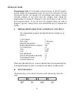
Page 6: ...setting follow each instructional step to program that setting I PROGRAMMING SEQUENCE AND DEFAULT SETTINGS The programming sequence and default factory settings are as follows LCD Contrast 5 Time Zon...

Page 7: ...o the Time Zone setting IV TIME ZONE SETTING 1 Press and hold the SET button for 5 seconds 2 LCD will show in the time LCD and the number setting will flash 3 Press and release the SET button again 4...

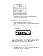
Page 8: ...3 Press and release the SET button twice 4 DST will appear to the right of the time and either 1 or 0 will flash 5 Press and release the IN button to select DST on or off DST 0 indicates that the fea...

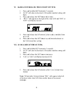
Page 9: ...trolled time on or off 6 Press and release the SET button to confirm and advance to the 12 24 hour time setting VII 12 OR 24 HOUR TIME SETTING 1 Press and hold the SET button for 5 seconds 2 LCD will...

Page 10: ...ation conducts a WWVB search every night between these hours and overrides any manually set time The WWVB tower icon appearing in the TIME LCD will flash when a signal search is in progress and a sign...

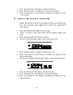
Page 11: ...button for 5 seconds 2 LCD will show in the time LCD and the number setting will flash 3 Press and release the SET button six times 4 The year will flash in the right section of the time LCD 5 Press...

Page 12: ...elect the temperature format XI SELECTING F OR C 1 Press and hold the SET button for 5 seconds 2 LCD will show in the time LCD and the number setting will flash 3 Press and release the SET button nine...

Page 13: ...ecast icon Areas that tend to have more air pressure change would set the sensitivity to 3 while areas that experience lower than normal air pressure change would set the sensitivity to 1 1 Press and...

Page 14: ...ather forecasting for 12 24 hours after the unit has been set up reset or moved from one altitude to another i e from one floor of a building to another floor In areas where the weather is not largely...

Page 15: ...y to rainy although it is possible for the change to occur quickly If the symbols do not change then the weather has not changed or the change has been slow and gradual B WEATHER TENDENCY ARROWS Other...

Page 16: ...Remote Temperature Sensors IV MINIMUM AND MAXIMUM TEMPERATURE RECORDS The WS 7168U keeps a record of the MINIMUM and MAXIMUM temperature and the time and date of their occurrence for both the indoor...

Page 17: ...y mode 2 Press the OUT button again once while MIN is still displayed twice otherwise MAX appears above the outdoor temperature and the LCD will flash indicating that the maximum temperature and the t...

Page 18: ...pas etc Note When setting up multiple units it is important to remove the batteries from all existing units in operation then to insert batteries first into all the remote temperature sensor units and...

Page 19: ...reset MOUNTING Note Before permanently mounting ensure that the indoor weather station is able to receive WWVB signals from the desired location Also extreme and sudden changes in temperature will de...

Page 20: ...nto the bracket B MOUNTING WITH ADHESIVE TAPE 1 With a nonabrasive solution clean and dry the back of the mounting bracket and the mounting surface to ensure a secure hold The mounting surface should...

Page 21: ...opriate location B WALL MOUNTING 1 Remove the table stand To do this pull down on the stand from the rear and rotate forward 2 Fix a screw not included into the desired wall leaving approximately 3 16...

Page 22: ...ies reinsert into remote temperature sensor first then the indoor weather station 2 Place the remote temperature sensor closer to the display 3 Be sure all batteries are fresh 4 Place the remote tempe...

Page 23: ...s and casings Do not submerge in water Immediately remove all low powered batteries to avoid leakage and damage Opening the casings invalidates the warranty Do not try to repair the unit Contact La Cr...

Page 24: ...performed by a La Crosse Technology Ltd authorized service center The original dated bill of sale must be presented upon request as proof of purchase to La Crosse Technology Ltd or La Crosse Technolog...

Page 25: ...ers only actual defects within the product itself and does not cover the cost of installation or removal from a fixed installation normal set up or adjustments claims based on misrepresentation by the...

Page 26: ...La Crosse Technology Made in China WS 7168U 081703 All rights reserved This handbook must not be reproduced in any form even in excerpts or duplicated or processed using electronic mechanical or chemi...

Reviews: