background image


8

NOTE:  You must insert the batteries into the third sensor within 30 seconds of 
reception of the second sensor. 


IMPORTANT: Transmission problems will arise if the setting for multiple sensors 
is not followed as described above. Should transmission problems occur, it is 
necessary to remove the batteries from all units and start again the set-up from 
step 1. 


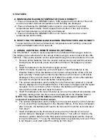
D. VIEWING AND OPERATING WITH MULTIPLE REMOTE SENSOR UNITS


1. To view the temperature of a different thermo-hygro sensor unit, press and release 

the 

SET/CH

 button.  A shift from one “boxed” number to the next should be 

observed on the right side of the OUTDOOR LCD.  

2. To view the Minimum/Maximum temperature & humidity: first select from which 

thermo-hygro sensor to read data (indicated by the “boxed” number).  Pressing and 
releasing the 

MIN/MAX

 button will toggle through the minimum and maximum 

indoor temperature, and the minimum and maximum outdoor temperature and 
humidity. 

3. To reset the Minimum/Maximum readings, press and hold the 

MIN/MAX 

button for 

5 seconds. 


III. MOUNTING 

Note:

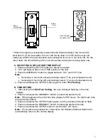
  To achieve a true temperature reading, avoid mounting in direct sunlight. We 

recommend that you mount the thermo-hygro sensor on an outside North-facing wall 
(under the eve of a house is ideal).  The sending range is 330 feet; obstacles such as 
walls, stucco walls, concrete, and large metal objects will reduce the range.  Place the 
Wireless Weather Station and thermo-hygro sensor in their desired locations before 
permanently mounting. 
 

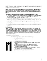
A. THERMO-HYGRO SENSOR 

The thermo-hygro sensor can be mounted in two ways: 

 with the use of screws, or 

 using the adhesive tape. 


A.  MOUNTING WITH SCREWS


1)  Remove the mounting bracket from the remote thermo-hygro 

sensor. 

2)  Place the mounting bracket over the desired location. 
3)  Through the three screw holes of the bracket, mark the 

mounting surface with a pencil. 

4)  Screw mounting bracket onto the mounting surface.  Ensure 

that the screws are flush with the bracket. 

5) Insert the thermo-hygro sensor into the bracket. 


Summary of Contents for WS-7220U-IT

Page 1: ...1 WS 7220U IT 915 MHz Wireless Weather Station Instruction Manual ...

Page 2: ...Display 5 Time Setting 5 Features 6 7 Minimum Maximum Temperature and Humidity 6 Resetting Minimum Maximum Temperature and Humidity 6 Adding Additional Thermo Hygro Sensors 6 Viewing Operating with Multiple Thermo Hygro Sensors 6 7 Mounting 7 Troubleshooting 7 8 Maintenance Care Instructions 8 Specifications 8 9 Warranty Information 9 10 ...

Page 3: ...ISSION offers you an immediate update every 4 seconds of all your outdoor data measured from the transmitters follow your climatic variations in real time This product offers 12 or 24 Hour Time Display Indoor Temperature F or C Connection w Sensor Icon Set Channel Button Outdoor Temperature F or C Outdoor Humidity RH Minimum Maximum Plus Button Low Battery Indicator ...

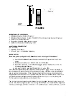
Page 4: ...Weather Station 4 DO NOT PRESS ANY BUTTONS FOR 15 MINUTES In this time the Wireless Weather Station and the thermo hygro sensor will begin to communicate with each other and the display will show both the indoor temperature and an outdoor temperature If the Wireless Weather Station does not display both temperatures after the 15 minutes please retry the set up as stated above After both indoor and...

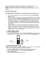
Page 5: ...e the indoor data is displayed user may proceed to the next step 3 After the batteries are inserted the Weather Station will start receiving data signal from the sensor The outdoor temperature and humidity should then be displayed on the Weather Station If this does not happen after 2 minutes the batteries will need to be removed from both units and reset from step 1 and the signal reception icon ...

Page 6: ... unit Selecting 24 hour time will automatically select C as your temperature unit 4 Press and release the SET CH button again to enter Time Setting D TIME SETTING 1 After exiting the 12 24 Hour Setting the hour will begin flashing in the time display 2 Press and release the MIN MAX button to select the desired hour Note PM will appear to the left of the time display for PM hours For AM hours that ...

Page 7: ...er Station Once the batteries are in place all segments of the LCD will light up briefly Following the indoor temperature and the time as 12 00 will be displayed If they are not shown in LCD after 60 seconds remove the batteries and wait for at least 60 seconds before reinserting them 4 The outdoor temperature and humidity from the first sensor channel 1 should then be displayed on the Weather Sta...

Page 8: ...maximum outdoor temperature and humidity 3 To reset the Minimum Maximum readings press and hold the MIN MAX button for 5 seconds III MOUNTING Note To achieve a true temperature reading avoid mounting in direct sunlight We recommend that you mount the thermo hygro sensor on an outside North facing wall under the eve of a house is ideal The sending range is 330 feet obstacles such as walls stucco wa...

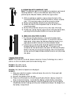
Page 9: ...ppropriate location and pull out on the attached stand 2 To wall mount push the table stand flat against the Wireless Weather Station if it isn t already flat Fix a screw not included into the desired wall and place the Wireless Weather Station onto the screw using the hanging hole on the backside Gently pull the Wireless Weather Station down to lock the screw into place TROUBLESHOOTING NOTE For p...

Page 10: ... scouring agents they may mark the displays and casings Do not submerge in water Do not subject the units to unnecessary heat or cold by placing them in the oven or freezer Opening the casings invalidates the warranty Do not try to repair the unit Contact La Crosse Technology for repairs SPECIFICATIONS Transmitting Frequency 915 MHz TEMPERATURE MEASURING RANGES Indoor 14 1 F to 139 8 F with 0 2 F ...

Page 11: ...td will pay all expenses for labor and materials for all repairs covered by this warranty If necessary repairs are not covered by this warranty or if a product is examined which is not in need or repair you will be charged for the repairs or examination The owner must pay any shipping charges incurred in getting your La Crosse Technology Ltd product to a La Crosse Technology Ltd authorized service...

Page 12: ...ply to you For warranty work technical support or information contact La Crosse Technology 2809 Losey Blvd S La Crosse WI 54601 Phone 608 782 1610 Fax 608 796 1020 e mail support lacrossetechnology com warranty work sales lacrossetechnology com information on other products web www lacrossetechnology com Questions Instructions Please visit www lacrossetechnology com 7220 All rights reserved This h...

Page 13: ... and found to comply with the limits for a Class B digital device pursuant to Part 15 of the FCC Rules These limits are designed to provide reasonable protection against harmful interference in a residential installation This equipment generates uses and can radiate radio frequency energy and if not installed and used in accordance with the instructions may cause harmful interference to radio comm...

Reviews: