(P/N)738.098 Rev A • 04/09
© copyright 2009
Kaba Mas LLC
page 4 of 5
5. Connect the cable coming from the Entry Device directly into the connector port marked ENT on the lock. (Figure 6)
DEAD BOLT OR SPRING BOLT LOCKS
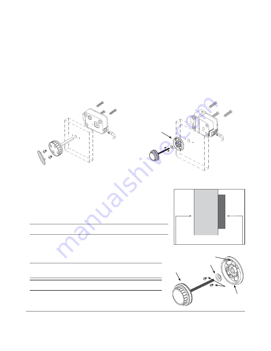
In order to use either the Dead bolt or Spring bolt locks, a method of retracting the bolt will be required. Knob Assembly - P/N 2666 -
(Figure 8) is recommended.
The drilling holes necessary to mount the lock correspond with the standard dimensions for mechanical locks. The spindle hole must
be well deburred and no sharp edges may remain. The holes required to mount the knob need to be drilled 1.25
"
apart and must be
centered over the spindle hole.
1. Locate, drill and tap holes to mount the Lock Assembly to the inside of the safe door using the installation template provided.
2. To install the Knob Assembly, remove the insert from the front of the knob.
3. Cut the spindle to a length of .820
"
(20.8mm) plus the mounting thickness.
4. Install the knob assembly using the two 8-32 X 5/16 phillips pan screws. (Figure 8)
5. Install the lock (always with the bolt extended) onto the spindle, placing it fl ush to the mounting surface.
6. Attach the lock using the three US 1/4"-20 (Metric M6X1) screws found in the hardware pack.
7. Connect the cable coming from the Entry Device directly into the connector port marked ENT on the lock. (Figure 8)
REDUNDANT MECHANICAL LOCKS
In order to use a Redundant Mechanical lock, a method of retracting the bolt is required.
Use of the VISIONGARD Dial (P/N 2085) is recommended (Figure 9). An entire range of
LA GARD dials is available for alternate dial options.
1. Locate, drill and tap holes to mount the Lock Assembly to the inside of the safe door
using the installation template provided.
2. Locate and drill the two holes for the dial ring to be mounted.
3. Attach the lock assembly to the door using the three US 1/4”-20 (Metric M6X1)
mounting screws provided. Tighten the mounting screws to a torque setting of 30
in./lbs. (3.4 N•m).
Note:
Ensure the lock assembly spindle hole is properly aligned with the spindle
through hole in the safe door.
4. Measure total mounting thickness (door thi mounting plate). (Figure 10)
5. Cut the spindle to a length of 1.125” (28.6mm) plus the total mounting thickness.
6. Mount the dial ring centered on the through hole, and attach to the safe door using the
two mounting screws supplied with the dial assembly. The opening index reference
mark must be in the twelve o’clock position. (Figure 11)
7. Place the dial bearing onto the dial ring.
WARNING:
The lock bolt MUST remain in the retracted position throughout the
installation procedure. To ensure this keep one fi nger over the bolt while installing
the dial spindle into the lock cam.
WARNING:
Ensure that you are properly grounded to protect the system card from
Electrostatic Discharge (ESD) damage before proceeding with the next steps.
8. Remove the two cover screws from the back cover of the lock assembly, and
remove the lock back cover. (Figure 12)
9. Carefully unplug the solenoid connector from the system card. (If applicable,
unplug the bolt switch connector from the system card.) (Figure 12)
Figure 8
Figure 9
Dial ring
Figure 10
DOOR
MOUNTING PLA
TE
Total Mounting Thickness = door thickness
+ mounting plate
Dial
Dial
Ring
Mounting
Screws
Dial Bearing
Opening
Index
Figure 11


