background image


26

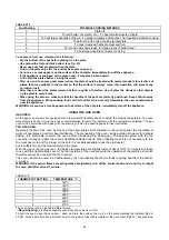
Therefore, it is normal for this light to turn on and off while the oven is working. There are 3 fixed positions beyond the 
250 °C setting: 
- the symbol 

 indicates that only the bottom element (1600W) has been turned on; 

- the symbol 

 indicates that only the top external element (1200W) has been turned on; 

- the symbol 

 indicates that only the grill element (1500W) has been turned on (see the specific paragraph). 


In these positions the temperature is not controlled by the thermostat. 

Warning! Oven light running for static oven. 

As for cookers with one control electric static oven, the oven lamp can be switched on thanks to the specific button and 
also every time that the oven is ignited trought the relative selector. 


USING THE ELECTRIC THERMOSTAT 

(COOKERS WITH A CONVENTIONAL ELECTRIC OVEN AND SEPARATE CONTROLS, WITH A 

VENTILATED CONVENTIONAL OVEN OR WITH A MULTIFUNCTION OVEN) 

The thermostat supplied with the relative models maintains a constant temperature inside the oven at a specific 
temperature setting ranging from 50°C to 250°C. Turn the knob (fig.32-33) clockwise and align the selected temperature 
indicated on the ring with the index etched on the control panel. Thermostat operation is indicated by an orange light 
which will turn off when the temperature inside the oven is 10°C greater than the temperature setting, and will turn on 
when the oven is 10°C less than the temperature setting. The thermostat can control the oven elements only if the 
relative switch is in one of the possible oven element operating modes: if the switch is in position 0, the thermostat has 
not effect on the oven elements, which remain off. 


USING THE 4 + 0 SWITCH 

(COOKERS WITH A VENTILATED CONVENTIONAL ELECTRIC OVEN) 

The 4 + 0 switch installed in the ventilated conventional oven models is used, along with the thermostat, to control the 
electric fan and the oven elements since they can be turned on by turning the 4 + 0 switch knob (fig.34) and the 
thermostat knob. Turning just one of the two knobs will not have any effect on the oven except to turn on the oven light or 
the electric fan when inserted. 
The electric oven is heated by 3 elements: one on the bottom and two on the top; turning the switch knob turns on the 
element relative to the symbol indicated on the ring but to be activated the thermostat knob must be turned until the 
orange light turns on indicating that the element has been turned on. Placing the switch knob on any of the four operating 
modes turns on the oven light, together with the relative element. Once the temperature and the elements to be used 
have been set, the oven elements are turned on and off by the thermostat; therefore, it is normal for the orange light to 
turn on and off while the oven is working. 
To turn off the electric oven set the switch knob to position 0 to prevent the thermostat from controlling the elements. 
Setting the thermostat knob to position 0 turns off the elements but it is still possible, using the switch, to turn on the 
electric fan and the oven light. 
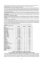
The switch has 4 different fixed positions corresponding to 4 different types of oven operation: 
- the symbol 

 indicates that the bottom element (1600W) and the top external element (1200W) and  


the electric fan have been turned on; 

- the symbol 

 indicates that the bottom element (1600W) and the top external element (1200W) have been turned on 

- the symbol   indicates that only the electric fan has been turned on; 
- the symbol 

 indicates that only the grill element (1600W) has been turned on. 

When the knob is set to one of these four positions, the oven light is always on, thus indicating that the oven is being 
energised. 


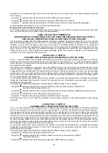
USING THE 9 + 0 SWITCH 

(COOKERS WITH A MULTIFUNCTION ELECTRIC OVEN) 

The 9 + 0 switch installed in the multifunction oven models is used, along with the thermostat, to control the electric fan 
and the oven elements since they can be turned on by turning the 9 + 0 switch knob (fig.35-36) and the thermostat knob. 
Turning just one of the two knobs will not have any effect on the oven except to turn on the oven light or the electric fan 
when inserted. The electric oven is heated by 4 elements: one on the bottom, two on the top or one circular; turning the 
switch knob turns on the element relative to the symbol indicated on the ring but to be activated the thermostat knob must 
be turned until the orange light turns on indicating that the element has been turned on. Placing the switch knob on any of 
the nine operating modes turns on the oven light, together with the relative element. Once the temperature and the 
elements to be used have been set, the oven elements are turned on and off by the thermostat; therefore, it is normal for 
the orange light to turn on and off while the oven is working. 
To turn off the electric oven set the switch knob to position 0 to prevent the thermostat from controlling the elements. 
Setting the thermostat knob to position 0 turns off the elements but it is still possible, using the switch, to turn on the 
electric fan and the oven light. 
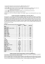
The switch has 9 different fixed positions corresponding to 9 different types of oven operation: 
- the symbol 

 indicates that only the oven light is turned on; 

- the symbol 

 indicates that the bottom element (1600W) and the top external element (1200W) 


 have been turned on; 

- the symbol 

 indicates that only the top external element (1200W) has been turned on; 

Summary of Contents for AMN805GEVSWE

Page 1: ...NSTRUCTIONS FOR FREE STANDING COOKERS 80x50 cm type MG MGV PAG 17 NOTICE D INSTALLATION D ENTRETIEN ET MODE D EMPLOI DE LA CUISINIERE A GAZ 80x50cm MODELE MG MGV PAG 31 Questo manuale d istruzione for...

Page 2: ...ore 9 0 forno elettrico multifunzione a comandi separati pag 12 Utilizzo del forno elettrico a convezione naturale pag 13 Utilizzo del forno elettrico statico a convezione ventilata pag 14 Utilizzo de...

Page 3: ...L INSTALLATORE L installazione tutte le regolazioni le trasformazioni e le manutenzioni elencate in questa parte devono essere eseguite esclusivamente da personale qualificato legge n 46 e D P R 447 U...

Page 4: ...denza impressa sullo stesso La tenuta del collegamento all apparecchio ed alla rete gas e garantita dal fissaggio del tubo flessibile tramite normali fascette per tubi flessibili in gomma Questo tubo...

Page 5: ...nuovo tipo di gas secondo quanto indicato nella tabella N 1 ATTENZIONE Dopo aver eseguito le suddette sostituzioni il tecnico dovr procedere alla regolazione dei bruciatori descritta nel paragrafo se...

Page 6: ...ervanza di queste disposizioni Quando il collegamento alla rete di alimentazione effettuato tramite presa Applicare al cavo di alimentazione se sprovvisto una spina normalizzata adatta al carico indic...

Page 7: ...e lo schienalone posteriore ATTENZIONE Nel caso di sostituzione del cavo di alimentazione l installatore dovr tenere il conduttore di terra pi lungo rispetto ai conduttori di fase ed inoltre dovr risp...

Page 8: ...a forno inibisce il funzionamento del grill elettrico che quindi non pu essere utilizzato con la ventola in funzione il simbolo indica il tasto di azionamento del girarrosto solo forno a gas il simbol...

Page 9: ...ni permanenti sulla superficie di appoggio della griglia non rimuovibili mediante normale lavaggio NOTE L utilizzo di un apparecchio di cottura a gas produce calore ed umidit nel locale in cui install...

Page 10: ...forno a gas pu essere abbinato al grill a gas oppure al grill elettrico per il cui uso si rimanda alle specifiche pagine FORNO A GAS VENTILATO Azionando la ventola forno tramite l apposito interrutto...

Page 11: ...ossono essere inserite indifferentemente le griglie o il vassoio Per evitare di sporcare eccessivamente il forno si consiglia di cuocere la carne o sul vassoio o sulla griglia che va inserita dentro i...

Page 12: ...serisce contemporaneamente alla relativa resistenza anche la lampada forno L accensione e lo spegnimento delle resistenze forno una volta impostata la temperatura e le resistenze che si vogliono far f...

Page 13: ...a manopola del termostato ed attendere prima di inserire gli alimenti che la spia arancione si spenga Il forno dotato di 4 guide a differenti altezze fig 30 nelle quali possibile posizionare indiffere...

Page 14: ...EPRE ARROSTO 230 3 4 40 50 CONIGLIO ARROSTO 230 3 60 80 TACCHINO ARROSTO 230 3 50 60 OCA ARROSTO 200 3 60 70 ANITRA ARROSTO 230 3 4 45 60 POLLO ARROSTO 230 3 4 40 45 PESCE 180 200 3 4 15 25 PASTICCERI...

Page 15: ...posizione di massima temperatura numero 8 Quindi premere la manopola del termostato versioni con accensione sottomanopola Attendere circa 10 secondi dopo l accensione completa del bruciatore e rilasci...

Page 16: ...lo premuto fino a selezionare l ora rilasciare il perno e girarlo in senso orario fino a posizionare la ghiera sul simbolo della campana barrata in questo modo funzioner solamente l orologio Per l uti...

Page 17: ...orno Caratteristica del forno la possibilit di smontare il vetro interno per poter effettuare la pulizia interna dei cristalli Tale operazione da eseguire a forno freddo e con panno umido avendo cura...

Page 18: ...pg 23 Using hot plates pg 23 24 Using the gas oven pg 24 25 Using the thernostat with switch in series pg 25 26 Using the electrical thernostat pg 26 Using the 4 0 switch Using the 9 0 switch pg 26 2...

Page 19: ...defined by the current national standards regarding room ventilation see Fig 3 These openings shall be built so that they cannot be clogged Indirect ventilation is also permitted by taking air from t...

Page 20: ...3 2580 NO Grill Butane G30 28 30 85 218 3 2580 NO Propane G31 37 85 214 3 2580 NO BURNER ADJUSTMENT Grill burner adjustment to adjust the grill burner loosen screw P and adjust the position X of the...

Page 21: ...2 HOT PLATES 3 X 2 5 mm ATTENTION The appliance conforms with the regulations of directives 90 396EEC Gas Directive regarding gas appliances for domestic use and the like 93 68 and 73 23 Low Voltage D...

Page 22: ...hot during use For glass doors Do not use abrasive cleaning products or metal spatulas with sharp edges to clean the oven door s glass since this could scratch the surface and the glass could break Do...

Page 23: ...ower is cut off the burners can be lit with matches When cooking foods with oil and fat which are very flammable the user should not leave the appliance unattended If the appliance is equipped with a...

Page 24: ...y device to adjust the cooking temperature The oven temperature is set by turning the knob counterclockwise to match the indicator with the temperature selected The gas oven can be combined with a gas...

Page 25: ...possible it is recommended to cook meat on the tray or on the shelf that has been inserted inside the tray The table below lists the general cooking times and the position of the tray for different t...

Page 26: ...have been set the oven elements are turned on and off by the thermostat therefore it is normal for the orange light to turn on and off while the oven is working To turn off the electric oven set the...

Page 27: ...determine any variations in the values reported in the table In any case it is recommended to follow the instructions of the specific recipe being used TABLE N 8 NATURAL CONVENTIONAL ELECTRIC OVEN CO...

Page 28: ...NTILATED ELECTRIC OVEN fig 37 When using the oven for the first time it should be operated for a maximum of 30 minutes at a temperature of about 250 to eliminate any odours generated by the internal i...

Page 29: ...b so that the relative symbol matches the indicator then press the thermostat knob models with ignition trough knob Wait about 10 seconds after the burner has been completely lit and then release the...

Page 30: ...finished To settle the clock you have to turn the pivot clockwise by pushing it till you have selected the suitable time release the pivot and turn it clockwise till you have positionned the ring on t...

Page 31: ...s For the removal of internal glass lock the hinges by inserting the nail that came in the hinges 22 Fig 47 48 then remove the inner glass as Fig 49 50 51 52 53 54 To reassemble the door to perform ta...

Page 32: ...ation des br leurs page 38 Utilisation des plaques elestriques page 38 39 Utilisation du four gaz page 39 40 Utilisation du thermostat avec commutateur en serie Utilisation du thermostat lectrique pag...

Page 33: ...ou directement l ext rieur cfr Fig 4 Au cas o il serait impossible d installer une hotte on peut utiliser un ventilateur mont sur une fen tre ou directement sur le mur externe mettre en route chaque...

Page 34: ...le br leur de son support tout en faisant attention ne pas ab mer la flamme d allumage et le thermocouple Fig 11 2 Utiliser la cl tubes hexagonale de 7 mm et remplacer l injecteur C par un autre adap...

Page 35: ...ion en vigeur Avant de proc der au branchement v rifier que Le voltage lectrique de l installation et des prises de courant sont compatibles avec la puissance maximale de l appareil cfr tiquette d ide...

Page 36: ...coupants pour nettoyer la vitre de la porte du four pour ne pas risquer d en rayer la surface voire de la briser Ne pas utiliser un nettoyeur vapeur pour le nettoyage de l appareil PROTECTION PORTE L...

Page 37: ...EN VITROC RAMIQUE TYPE PLACA DIMENSION mm Placa lectrique normale 110 700W Placa lectrique normale 180 1500W DESCRIPTION PANNEAU DE CONTROLE Sur le panneau de contr le en correspondance de chaque bou...

Page 38: ...liments avec de l huile ou autres mati res grasses facilement inflammables l utilisateur ne doit pas s loigner de l appareil Si l appareil est dot d un couvercle en verre celui ci peut clater sous l a...

Page 39: ...mbin un grilloir gaz ou un grilloir lectrique dont l utilisation est expliqu e dans les pages correspondantes FOUR A GAS A CHALEUR TOURNANTE En actionnant le ventilateur du four par l interrupteur app...

Page 40: ...s d aliments Ces informations ne sont donn es qu titre indicatif et ne sauraient remplacer l exp rience ou les go ts personnels Il est de toutes fa ons conseill de suivre les indications report es sur...

Page 41: ...oyant de couleur orange indiquant l enclenchement de la r sistance s allume Pla ant le bouton du commutateur Fig 34 sur une des quatre modalit s de fonctionnement la lampe du four s enclenche en m me...

Page 42: ...vant d utiliser le four pour la premi re fois le chauffer une temp rature de 250 C pendant 30 minutes au maximum afin de chasser les odeurs produites par l isolement interne Pendant le fonctionnement...

Page 43: ...210 3 35 40 PAIN DE GENES 160 180 3 50 55 BRIOCHES 160 180 3 25 30 GENOISE 200 230 3 20 30 SAVARIN 160 180 3 30 40 MILLE FEUILLES 180 200 3 15 20 GALETTES AUX RAISINS 230 3 25 35 STRUDEL 165 3 20 30 B...

Page 44: ...le symbole avec le rep re et continuant appuyer sur le bouton approcher une allumette au br leur Une fois allum attendre 10 secondes et rel cher le bouton V rifier que le br leur est allum en cas con...

Page 45: ...N lors de son utilisation l appareil devient chaud Faire attention ne pas toucher les l ments chauffants situ s l int rieur du four ATTENTION les parties accessibles peuvent devenir tr s chaudes penda...

Page 46: ...La porte du four avec un verre viss Nettoyage du verre l int rieur du four Le verre l int rieur du four peut tre d mont en d vissant simplement les 2 vis B voir Fig 44 45 pour le nettoyer Cette op rat...

Page 47: ...47 Fig 3 Fig 4 Fig 5 Fig 6 Fig 7 Fig 8 Fig 9 Fig 10 Fig 11 Fig 12...

Page 48: ...48 Fig 13 Fig 14 Fig 15 T Fig 16 Fig 17 Fig 18 Fig 19 Fig 20 Fig 21 Fig 22 Fig 23 Fig 24...

Page 49: ...49 Fig 25 Fig 26 Fig 27 Fig 28 Fig 29 Fig 30 Fig 31 Fig 32 Fig 33 Fig 34 Fig 35 Fig 36 Fig 37 Fig 38 Fig 39 Fig 40...

Page 50: ...50 Fig 41 Fig 42 Fig 43 Fig 44 Fig 45 Fig 46 Fig 47 Fig 48 Fig 49 Fig 50...

Page 51: ...51 Fig 51 Fig 52 Fig 53 Fig 54 Fig 55 Fig 56...

Page 52: ...52 Fig 57 Fig 58 Fig 59 Cod 310914...

Reviews: