14
3
Operation
3.1
Starting the AUPS
All equipment is shipped from the factory fully checked and adjusted based on the customer order. Do not make
any adjustments unless the equipment has been powered-up and the settings have been determined to be
incorrect.
3.1.1 Checking the Installation
Before attempting to start up the AUPS, check and verify that all connections are correct. Check that all
terminations and contacts are tightened securely. Check that the transformer is set for the correct input voltage
and that the input frequency matches the nameplate of the system. Check that the battery voltage matches the
DC input voltage on the nameplate of the system.
WARNING:
The AUPS is default set based on 12, 24, or 60 lead acid cells for 24VDC, 48VDC, or
125VDC respectively. The alarm and voltage settings must coincide with the battery type and cells
used for the AUPS system. Refer to Table 8 for suggested values and Sections 3.6.1.1 and 3.6.1.2 for
output and alarm threshold adjustments.
3.1.2 Starting/Stopping the AUPS
Once proper connections are established, the AUPS may be energized. For proper starting and stopping of the
AUPS, follow the procedures below:
Starting the AUPS Procedure
1. Turn all of the system
’
s breakers and the inverter ON/OFF switch to the
OFF
position. Set the bypass switch
to AUTO mode.
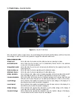
2. Assure the red Reverse Polarity LED is not lit.
3. Apply AC power to the Rectifier section and turn the Rectifier AC breaker to the
ON
position. At this point,
the rectifier will slowly ramp up and go through startup sequence. DC voltage and current should be
displayed on the front panel of the rectifier section. Full ramp up sequence must be completed before
moving forward.
4. Turn the Battery breaker to the
ON
position.
5. Push and hold the Pre-Charge button until the green READY LED illuminates. The green READY LED will
remain illuminated.*
NOTE:
Charging capacitors may take up to a minute. (Depending on the DC voltage bus and the total input
capacitance of the system)
6. Release the Pre-Charge button and immediately turn the Inverter DC breaker to the
ON
position.
7. Turn the ON/OFF switch (inverter section) to the
ON
position. The inverter should ramp up, but the inverter
display will not energize.
8. Turn the Inverter AC breaker to the
ON
position. All LEDs and the display should go through a startup
sequence on the front panel of the inverter section. After the startup sequence, Load AC voltage should be
displayed.
9. Apply AC power to the Alternate AC source (Bypass) and turn the Bypass AC breaker to the
ON
position.
Within a few seconds, the PHASE LOCK LED should illuminate. At this point, two AC sources should be
operating in sync.
CAUTION:
The start-up instructions must be followed in the correct order before restarting the AUPS or
damage to the system may occur.
*NOTE:
If the green READY LED does not light, check the battery voltage against the system nameplate. If the
red REVERSE POLARITY LED illuminates, the battery has not been installed as indicated. Disconnect the battery
wires immediately or damage to the AUPS may occur.
Summary of Contents for 7.5K-A1-BD3-125V100A
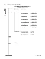
Page 30: ...24 3 6 3 Rectifier Customer Configuration Menu AUPS Rectifier Customer Configuration Menu ...
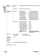
Page 31: ...25 ...
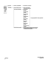
Page 32: ...26 ...


