17
NEGATIVE GROUND ALARM
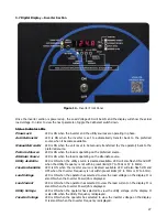
will trigger and the red NEGATIVE GROUND FAULT LED will turn on if 1.2mA or
greater current is measured between the negative terminal of the battery and earth ground. The alarm will clear
once the negative ground condition is no longer present. If the rectifier has Ground Detection disabled, this
alarm will not function.
POSITIVE GROUND ALARM
will trigger and the red POSITIVE GROUND FAULT LED will turn on if 1.2mA or
greater current is measured between the positive terminal of the battery and earth ground. The alarm will clear
once the positive ground condition is no longer present. If the rectifier has Ground Detection disabled, this
alarm will not function.
AC POWER FAIL ALARM
will trigger, the green AC ON LED will turn off, and the red AC FAILURE LED will turn
on when the AC power to the rectifier is lost. The alarm will automatically reset when AC power is restored to
the rectifier. When AC power is lost, the front panel display and indicators will remain powered by the
connected batteries.
SUMMARY ALARM
is triggered and the SUMMARY LED will turn on when any of the following alarms are
activated:
Low DC Voltage
Positive Ground*
High DC Voltage
Negative Ground*
Low DC Current*
AC Failure*
* Optional to include in Summary Alarm
LOW DC CURRENT ALARM
will trigger and the amber LOW DC CURRENT LED will turn on if the DC current of
the rectifier falls below the alarm threshold for longer than 5 seconds. This is usually caused by the inverter
section being off and a fully charged battery. This could also be the result of maladjustments of the output
voltage settings. This alarm can be disabled if considered a nuisance alarm.
PHASE LOCKED
LED will turn on and the relay contacts will trigger if the inverter and utility (AC Bypass)
sources are synchronized within the phase window.
UTILITY AVAILABLE
LED will turn on and the relay contacts will trigger if the utility (AC Bypass) source is
deemed available. This LED will also flash ON and OFF if the inverter frequency is not within the preset limits
(47 to 53 Hz for 50Hz inverters or 57 to 63 Hz for 60Hz inverters).
INVERTER AVAILABLE
LED will turn on and the relay contacts will trigger if the inverter source is deemed
available. This LED will also flash ON and OFF if the inverter frequency is not within the preset limits (47 to 53
Hz for 50Hz inverters or 57 to 63 Hz for 60Hz inverters).
LOAD ON PREFERRED SOURCE
LED will turn on and the relay contacts will trigger if the AUPS is operating
on the preferred source. The preferred source may be set to either Inverter or Utility (AC Bypass).
LOAD ON ALTERNATE SOURCE
LED will turn on and the relay contacts will trigger if the AUPS is operating
on the alternate source. The preferred source may be set to either Inverter or Utility (AC Bypass).
Most alarms have adjustable time delays to energize; ranging from 0 through 255 seconds. Refer to Table 8 and
9 for the factory setting of each alarm.
NOTE:
All alarms automatically reset when the alarm condition is corrected. However, the High Voltage
Shutdown must be reset manually by resetting the Rectifier AC breaker.
Summary of Contents for 7.5K-A1-BD3-125V100A
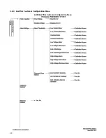
Page 30: ...24 3 6 3 Rectifier Customer Configuration Menu AUPS Rectifier Customer Configuration Menu ...
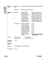
Page 31: ...25 ...
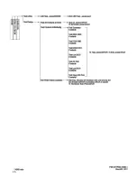
Page 32: ...26 ...


