27
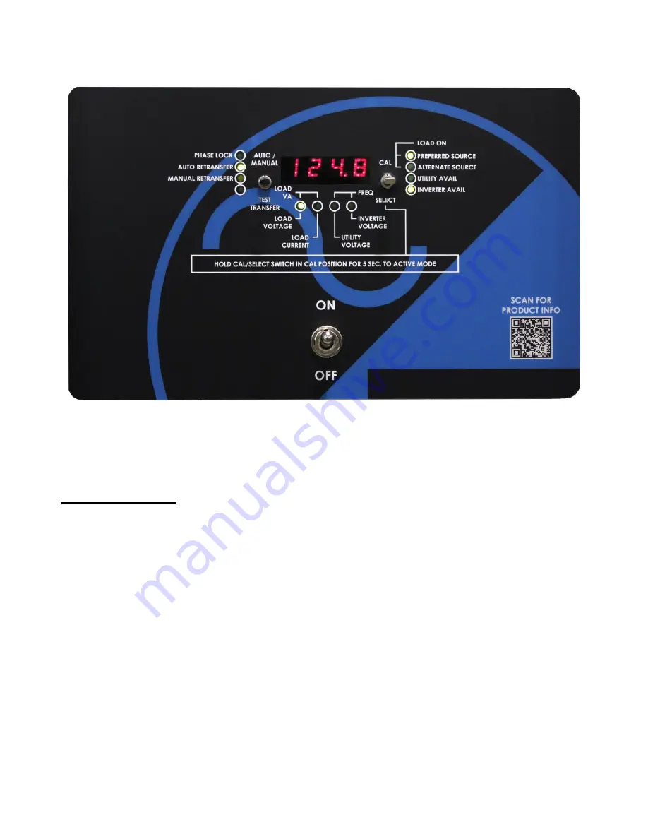
3.7 Digital Display
–
Inverter Section
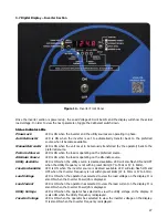
Once the inverter section is powered up, the Load Voltage LED will be ON and the display will show the actual
load voltage. In order to view the next parameter, toggle the Cal/Select switch down.
Status Indicator LEDs
Phase Lock
LED is ON when the inverter and the utility sources are operating in phase.
Auto Retransfer
LED is ON when the inverter is set to automatically transfer back to the preferred
source when it becomes available.
Manual Retransfer
LED is ON when the unit is set to be manually transferred (by the operator) back to the
preferred source.
Preferred Source
LED is ON when the load is operating on the preferred source.
Alternate Source
LED is ON when the load is operating on the alternate source.
Utility Available
LED is ON when the utility source is deemed available. LED will also flash ON and OFF
when the Utility Frequency is not within preset limits (47 to 53Hz or 57 to 63Hz).
Inverter Available
LED is ON when the inverter source is deemed available. LED will also flash ON and
OFF when the Inverter Frequency is not within preset limits (47 to 53Hz or 57 to 63Hz).
Load Voltage
LED is ON when the operator has selected to view the load voltage on the display. It is
also ON when the Inverter Power/VA is displayed.
Load Current
LED is ON when the operator has selected to view the load current on the display. It is
also ON when the Inverter Power/VA is displayed.
Utility Voltage
LED is ON when the operator has selected to view the utility voltage on the display. It
is also ON when the Utility Frequency is displayed.
Inverter Voltage
LED is ON when the operator has selected to view the inverter voltage on the display.
It is also ON when the Inverter Frequency is displayed.
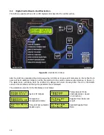
Figure 14 -
Inverter Front Panel
Summary of Contents for 7.5K-A1-BD3-125V100A
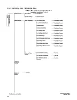
Page 30: ...24 3 6 3 Rectifier Customer Configuration Menu AUPS Rectifier Customer Configuration Menu ...
Page 31: ...25 ...
Page 32: ...26 ...

