28
3.8
Adjusting Parameters
–
Inverter Section
All equipment is shipped from the factory fully checked and adjusted based on the customer order. Do not make
any adjustments unless the equipment has been powered-up and the settings have been determined to be
incorrect. If the settings have been determined to be incorrect, adjustments may be made as detailed below.
3.8.1 Customer Calibration Mode
Customer Calibration may be entered by holding the Cal/Select switch located on the front panel in the up
position for five (5) continuous seconds. Upon entry,
the display will show “CAL”.
The calibration modes work
such that the software will execute each calibration task in a predefined sequence advancing to the next
calibration setting only when the user toggles up on the Auto/Manual switch.
NOTE:
It is important to be aware that transfers are disabled in the calibration modes.
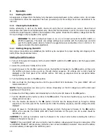
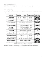
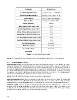
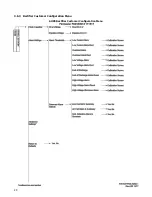
The Customer Calibration menu is as follows:
NOTE:
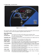
Adjustments are made using the Cal/Select switch on the front panel; up to increase and down to
decrease. Toggle the Re-Transfer switch up to advance to the next setting.
Preferred Source
The preferred source may be set to either Utility or Inverter. The displ
ay will alternate between “
-PS-
”
and the
preferred source selection which will be either “
UtIL
” for utility or “In” for inverter.
Load Voltage Window Upper Limit
The upper allowable limit for the Load Voltage signal may be set in terms of percent. The maximum allowable
upper setting is +30% and the minimum allowable upper setting is +10%. The default is +20%. The setting is
adjustable in 1% increments.
The display will alternate between “
-
LVH” and
the actual upper limit setting.
Load Voltage Window Lower Limit
The lower allowable limit for the Load Voltage signal may be set in terms of percent. The maximum allowable
lower setting is -30% and the minimum allowable lower setting is -10%. The default is -20%. The setting is
adjustable in 1% increments.
The display will alternate between “
-
LVL”
and the actual lower limit setting.
Utility Voltage Window Upper Limit
The maximum allowable/acceptable limit on the Utility Voltage defaults to the Output Voltage setting +10%.
Thus, an inverter with an output voltage of 120 Volts will have a default setting of approximately 132 Volts.
There are no limits on max or min settings for this. The display units are in Volts-RMS. Due to display
resolution, the ability to adjust this setting to an exact voltage may not be possible. Inverters with higher output
voltages will have less accurate adjustments than those inverters with lower output voltages. The display will
alternate between
“
-UL
H” and the upper
limit setting.
Utility Voltage Window Lower Limit
The minimum allowable/acceptable limit on the Utility Voltage defaults to the Output Voltage setting -10%.
Thus, an inverter with an output voltage of 120 Volts will have a default setting of approximately 108 Volts.
There are no limits on max or min settings for this. The display units are in Volts-RMS. Due to display
resolution, the ability to adjust this setting to an exact voltage may not be possible. Inverters with higher output
voltages will have less accurate adjustments than those inverters with lower output voltages. The display will
alternate between
“
-UL
L” and the lower limit setting.
Summary of Contents for 7.5K-A1-BD3-125V100A
Page 30: ...24 3 6 3 Rectifier Customer Configuration Menu AUPS Rectifier Customer Configuration Menu ...
Page 31: ...25 ...
Page 32: ...26 ...

