33
4
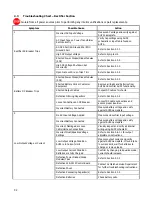
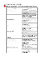
High Output Voltage or Current
Incorrect, Damaged or Loose
Cable/Harness Connections
Visually inspect and verify all internal
wiring using AUPS schematic.
Incorrect Battery Connected
Measure battery voltage and verify
against AUPS nameplate.
Incorrect Float/Equalize Voltage
Settings
Refer to Section 3.6.1.1 for output
adjustment instructions.
Defective S2A-341S Control Board
Contact La Marche Service Department
for further troubleshooting instructions.
Defective Batteries
Check battery cells.
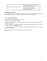
Open Gate or Wire on Triac TR-1
Refer to Section 4.3.3.
Ordering Replacement Parts
Contact La Marche to place an order for spare or replacement parts.
To order replacement parts; please provide
the model and serial number of the AUPS system, the part needed, and the quantity required.
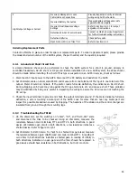
4.3.1 Ground and Short Circuit Test.
A simple ohmmeter check can be performed to check the AUPS system for a short to ground, primary to
secondary breakdown, AC-DC short, or DC ground. Before installation of a new AUPS system, the above checks
should be made before installing. If a short of this type is suspected on an AUPS in service, check as follows:
1.
Disconnect AC input power to the AUPS. Disconnect the DC battery and loads from the AUPS.
2.
Set ohmmeter scale on ohms scale RX100 and measure from one terminal of the input to one terminal of the
output. Meter should not indicate. If the meter reads full scale deflection, this indicates an AC-DC short.
During shipping, an AC wire may rub against the DC lugs, terminals, etc. and cause a short. These problems
may be eliminated by being very careful in inspecting the wiring to assure the AC wires are not touching the
DC wiring.
3.
Check the input terminals to ground and check the output terminals ground. If the meter indicates full scale
deflection, a wire is touching a metal part of the AUPS. Look for wires that are near any metal part and
inspect for possible breakdown caused by shipping. The heatsink of the diodes and the control charger are
insulated from ground through the mounting legs.
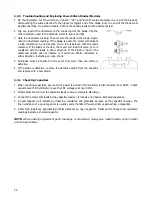
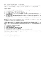
4.3.2 Troubleshooting the TRIAC
1.
On the ohmmeter, set the switches on “ohms”, “DC”, and “Rx10,000” scale
and disconnect the triac to be checked. Using an ohmmeter, measure the
resistance between main terminals, MT1 and MT2 in both directions. A good
device will indicate open circuit in both directions, a low resistance indicates a
shorted device. Refer to figure on right.
2.
Set ohmmeter to Rx100 scale. To check for a shorted triac gate lead, measure
the resistance between gate (GATE) lead and main terminal MT1. A reading of
zero ohms in both directions indicates a shorted gate. A reading of infinity in
both directions indicates an open gate and the triac should be replaced. A
good device should have resistance in both directions, but not zero ohms.
Summary of Contents for 7.5K-A1-BD3-125V100A
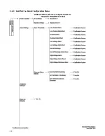
Page 30: ...24 3 6 3 Rectifier Customer Configuration Menu AUPS Rectifier Customer Configuration Menu ...
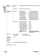
Page 31: ...25 ...
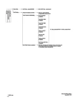
Page 32: ...26 ...

