37
7
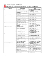
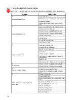
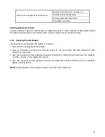
Inverter’s AC Load Supplied by Wrong Source
Defective SCR Module, refer to Section 4.5.1
Defective Electric Transfer Switch
Defective Mechanical Static Switch
Overloaded Prime Source
Ordering Replacement Parts
Contact La Marche to place an order for spare or replacement parts.
To order replacement parts; please provide
the model and serial number of the AUPS system, the part needed, and the quantity required.
4.5.1 Checking the SCR Module
The procedure for checking the SCR module is as follows:
1.
Disconnect the wiring going to the module.
2.
Using an ohmmeter, the three main terminals (A1K2, K1, A2) you should read high resistance in both
directions on your meter.
3.
Gate (G1) should read a high resistance between the top (A1K2), bottom (A2) terminals and a low resistance
(10 Ohm - 40 Ohm) to the middle (K1) terminal.
4.
Gate (G2) should read a high resistance between the middle (K1) and (A2) terminal and a low resistance
between terminal (A1K2).
NOTE:
A wiring diagram of the module is located on the side of the component.
Summary of Contents for 7.5K-A1-BD3-125V100A
Page 30: ...24 3 6 3 Rectifier Customer Configuration Menu AUPS Rectifier Customer Configuration Menu ...
Page 31: ...25 ...
Page 32: ...26 ...

