


1
Model Scope/General Description
The La Marche Model A31 is a transistorized DC to AC inverter designed to power an AC load.
The Model A31 will provide a sine wave output with approximately 5% total harmonic distortion into AC loads
with power factors up to 0.8 over a wide DC input range.
The ferroresonant output transformer provides input to output isolation, output regulation, current limiting, and
filtering. The DC input from the battery source is switched by transistors in all solid-state electronic circuitry to
produce a sine wave output.
The DC input sources are sensed for low and high voltage conditions, the unit is turned off automatically if the
DC input is not within the proper range.
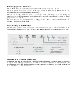
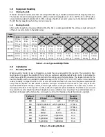
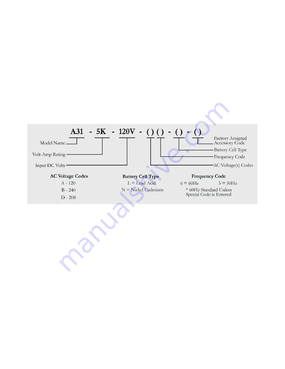
Understanding the Model Number
The A31 model number is coded to describe the features that are included. Find the model number on the
nomenclature nameplate of the inverter. Follow the chart below to determine the configuration of the inverter.
Optional Accessories Included in the Inverter
This inverter may have been outfitted with a number of optional accessories or option packages. To determine
the options included (if any) refer to the cover page of the manual package. If the manual package that is included
with the inverter is no longer available, contact La Marche and provide the model or serial number of the inverter
to receive a list of the included accessories.


