23
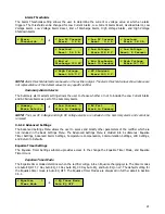
3.6.1.4 Return to Defaults
The 4
th
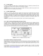
option in the Settings Menu is “Return to Defaults”. This option resets all user
-adjustable settings to the
factory defaults. It is important to note that the factory defaults are not necessarily the correct settings for the
specific DC system. Before the AUPS is shipped, adjustments are made at the factory using the same calibration
procedure. If the rectifier is reset to default, these factory changes may be reset.
Saving Settings
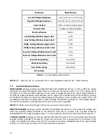
At any point, the user can press the BACK button from the main Settings Menu to exit the Settings Menu.
When the back button is pressed (on the main Settings Menu), the user is prompted if they would li
ke to “Exit
and Save Settings?”
If the BACK button is pressed again, the control board will return to the Settings Menu. If
YES
is selected, the display will read “Saving Settings”, the menu will be
exited and settings saved. If NO is
selected, the user is
prompted to “Exit without
Saving?” From this screen, if YES
is selected, the user will be
returned to the DC output display and all changes to the settings will not be saved. If NO is selected, the user
will be returned to the Settings Menu.
3.6.2 Test Menu
All equipment is shipped from the factory fully tested and operational. As part of planned maintenance, users
may want to be able to re-test functionality of the alarm LEDs and relays. The Test Menu allows the user to test
both the LEDs on the display board as well as any alarm relay contacts.
3.6.2.1 Test LEDs
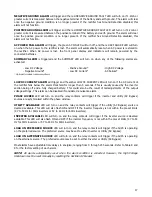
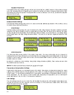
The Test LEDs menu allows the user to run a basic lamp test on the rectifier. After selecting this menu, press
the ENTER button to light all of the LEDs on the display membrane. To end the LED test, press back.
NOTE:
Any additional LEDs on auxiliary boards will not be affected by this LED test.
3.6.2.2 Test Relays
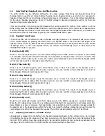
The test relays menu allows the user to test the functionality of the alarm relay contacts. The menu allows for
each contact to be tested individually, or all at once. When a relay is being tested, its contacts will change state.
This means if a relay is in alarm state, it will revert to the non-alarm state during relay testing. The HVSD alarm
is not included in either of the other tests, but instead, has its own test menu.
When an alarm relay is being tested, the corresponding LED on the membrane will change state. There are no
relay contacts for the OVERLOAD/CURR. LIMIT or END OF DISCHARGE alarms; these LEDs will not be lit under
the relay test. As with the LED test, once the appropriate selection is made, press the ENTER button to start the
test and the BACK button to end the test.
< Test HVSD >
Alarm Contacts
< Test Contacts>
Individually
< Test ALL >
Contacts at Once
< Test >
Relays
< End LED Test
Press BACK
< LED Test
Press ENTER
< Test >
LEDs
< Exit without
Saving? YES
< Exit and Save
Settings? NO
< Return to >
Defaults
Summary of Contents for AUPS-2K-A1-ABD1-24V150A
Page 30: ...24 3 6 3 Rectifier Customer Configuration Menu AUPS Rectifier Customer Configuration Menu...
Page 31: ...25...
Page 32: ...26...


