background image

INSTRUCTION MANUAL FOR PC63 CAGE 

Page 7 of 10 

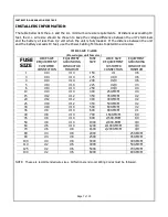
INSTALLERS INFORMATION


The table below lists the a.c. and the d.c. minimum wire size requirements.  At distances exceeding 10 
feet, the d.c. wire size should be chosen to keep the voltage difference between the unit's terminals 
and the battery at less than 1/2 volt when the unit is fully loaded.  If the distance between the unit 
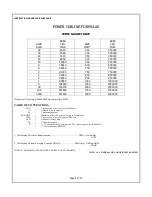
and the battery exceeds 10 feet, use the Power Cabling Formulas to determine wire size. 


WIRE SIZE TABLE 

(Based upon unit fuse size) 

FUSE 

SIZE 

WIRE SIZE 

REQUIREMENT 

CUSTOMER 

CONNECTION 

EQUIPMENT 

GROUNDING 

CONDUCTOR 

MINIMUM 

FUSE 

SIZE 

WIRE SIZE 

REQUIREMENT 

CUSTOMER 

CONNECTION 

EQUIPMENT 

GROUNDING 

CONDUCTOR 

MINIMUM 

#14 

#14 

150 

#1 

#6 

#14 

#14 

175 

#1/0 

#6 

#14 

#14 

200 

#2/0 

#6 

#14 

#14 

225 

#2/0 

#4 

#14 

#14 

250 

#4/0 

#4 

10 

#14 

#14 

300 

250-MCM 

#4 

15 

#12 

#12 

350 

350-MCM 

#2 

20 

#12 

#12 

400 

400-MCM 

#2 

25 

#10 

#12 

450 

500-MCM 

#2 

30 

#10 

#10 

500 

600-MCM 

#2 

35 

#8 

#10 

600 

900-MCM 

#1 

40 

#8 

#10 

700 

1500-MCM 

1/0 

45 

#8 

#10 

800 

2/500-MCM 

1/0 

50 

#8 

#10 

1000 

2/800-MCM 

4/0 

60 

#6 

#10 

1200 

2/1000-MCM 

4/0 

70 

#6 

#8 

1600 

2/2000-MCM 

4/0 

80 

#4 

#8 

2000 


250-MCM 

90 

#4 

#8 

2500 


350-MCM 

100 

#4 

#8 

3000 


400-MCM 

110 

#2 

#6 

4000 


500-MCM 

125 

#2 

#6 

5000 


700-MCM 

130 

#2 

#6 

6000 


800-MCM 


NOTE:  These are recommended wire sizes.  All National and Local Wiring Codes must be followed. 

Summary of Contents for PC63 Series

Page 1: ...OR PC63 CAGE Page 1 of 10 INSTRUCTION MANUAL FOR PC63 CAGE ECN DATE CPN106833 16816 6 05 106 BRADROCK DRIVE DES PLAINES IL 60018 847 299 1188 FAX 847 299 3061 ISSUE DATE 15689 12 02 INSTRUCTION DRAWIN...

Page 2: ...THE INSTRUCTIONS EXACTLY To reduce risk of battery explosion follow these instructions and those published by the battery manufacturer and manufacturer of any equipment you intend to use in the vicin...

Page 3: ...orrode and damage equipment A sealed maintenance free or valve regulated lead acid VRLA may be placed below this equipment Never allow the battery electrolyte to drip on this unit when reading the spe...

Page 4: ...to La Marche Mfg may void warranty service for any physical damages reported for repair HANDLING WARNING Equipment can be very heavy and top heavy Use adequate manpower or equipment for handling Unti...

Page 5: ...4V A63 24V A63 PC63 30 48V 130V 48V A63 48V A63 TPCD DISTRIBUTION CENTER PC63 60 24V 130V 24V A63 24V A63 TPCD DISTRIBUTION CENTER PC63 120 12V 130V 12V A63 12V A63 12V A63 12V A63 Input DC The A63 mo...

Page 6: ...ept a TPCD connect the negative wire from the battery must be connected to the terminal marked negative and the positive wire from the battery must be connected to the terminal marked positive on the...

Page 7: ...ENT CUSTOMER CONNECTION EQUIPMENT GROUNDING CONDUCTOR MINIMUM FUSE SIZE WIRE SIZE REQUIREMENT CUSTOMER CONNECTION EQUIPMENT GROUNDING CONDUCTOR MINIMUM 1 14 14 150 1 6 3 14 14 175 1 0 6 4 14 14 200 2...

Page 8: ...enotes all sizes larger than 0000 are expressed in MCM TABLE OF CONVENTIONS CMA Cross section of wire in circular MIL area A Ultimate drain in amperes LF Conductor loop feet MAX AMP Maximum allowable...

Page 9: ...ers and alarms for accuracy 4th Year REPEAT ABOVE WITH THE ADDITION OF 1 Check relay contacts for pitting or corrosion 2 Check capacitors for leakage 7th Year REPEAT ALL WITH THE ADDITION OF 1 Filter...

Page 10: ...lity for proper installation installation adjustments and service arrangements Should minor adjustments be required the local La Marche Sales Representative should be contacted to provide this service...

Reviews: