background image

Page 3

4

· Provides most comfortable option.  Maintains consistent hot water availability during specified times.

· Timer can be manually customized or programmed to automatically learn daily usage patterns.

· Ability to optimize by using Installer Mode function 3: RT to adjust loop temperature for maximum comfort

and safety.

Recirculation Mode

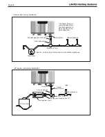
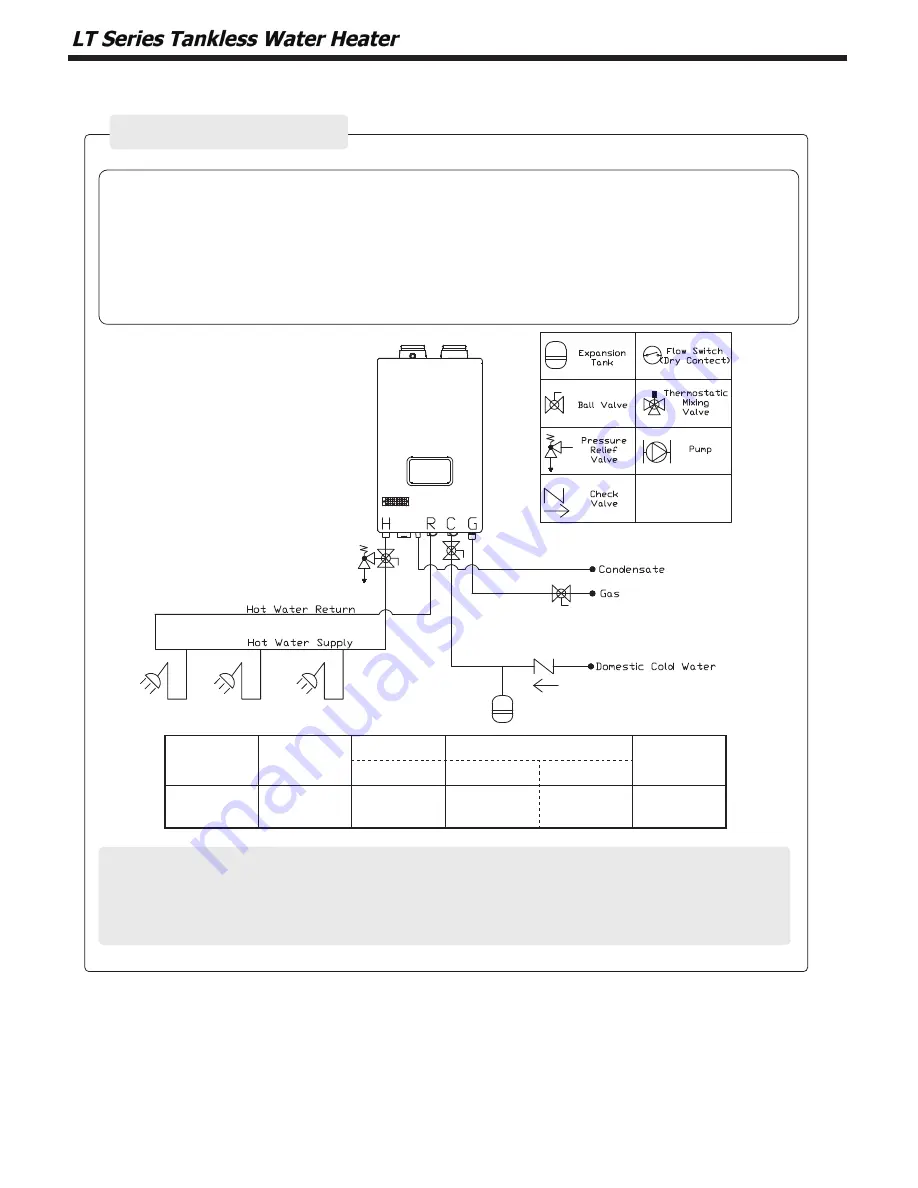
The recirculation pipe must be installed in the field in order to apply the ‘External Mode’.

This mode allows the water heater recirculation pipes to be warmed up and serving as the 

freeze protection function.

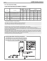
[ External Mode]

Dedicated 

Return Line

Accessory

Setting

Maximum Loop Length

Controlled by

11 : RC

1/2"

3/4"

YES

-

ON

200' (60m)

500' (150m)

Timer

Summary of Contents for LT Series

Page 1: ...essional service technician qualified in water heater installation and maintenance Improper installation and or operation could create carbon monoxide gas in flue gases which could cause serious injur...

Page 2: ...stics 57 SECTION 8 Maintenance 8 1 General Maintenance 58 SECTION 9 Installation Check 9 1 Quick View 59 9 2 Final check lists 64 SECTION 10 LT Series Warranty 4 1 Location and Clearances 12 4 2 Wall...

Page 3: ...has shown that most operating problems are caused by improper installation All installations must be made in accordance with 1 American National Standard Z223 1 NFPA54 Latest 1 2 Included with the Uni...

Page 4: ...ny part has been under water Immediately call a qualified service technician to inspect the appliance and to replace any part of the control system and any gas control that may have been under water S...

Page 5: ...G 3 5 WC to 10 5 WC LP 8 0 WC to 14 WC Manifold Pressure Gas Type NG LP Low Fire 2 VENT 0 1 WC 0 05 WC 3 VENT 0 1 WC 0 05 WC High Fire 2 VENT 0 20 WC 0 30 WC 3 VENT 0 20 WC 0 30 WC Power Supply Main S...

Page 6: ...163mm 17 3 440mm 8 9 226mm A C D I E H F G B Description Size A Exhaust 2 PVC B Air Intake 2 PVC C Hot Water 3 4 NPT D Condensate 1 2 NPT E Recirculation Return Connection 3 4 NPT F Cold Water Connect...

Page 7: ...utlet 13 Condensate Trap Cleanout 14 Recirculation Return Water Connector Name of Component 15 Cold Water Inlet 16 Gas Inlet 17 Main Controller 18 Water Adjustment Valve 19 Control Panel 20 Manual Pow...

Page 8: ...If you do not follow these instructions exactly a fire or explosion could result causing property dam age personal injury or loss of life A This appliance does not have a pilot It is equipped with an...

Page 9: ...g flood physical damage or any other damaging condition that might affect the operation of the unit Water Heater must be checked by a qualified technician before resuming operation DO NOT use this Wat...

Page 10: ...k that the manual gas shut off valve that supplies the water heater is opened 5 Check for a gas leak at the gas connection with soapy water 6 Check the area around the appliance and remove any combust...

Page 11: ...fail due to the exposure to moisture Do not disassemble the water heater If repair is required call your local qualified technician CAUTION Scalding Risk The use of an anti scald mixing valve at the h...

Page 12: ...installed in a narrow space or corner please ensure that there is sufficient space for service and maintenance access For regular maintenance there should not be any problem to approach gas and water...

Page 13: ...rill bit into the wall through the Bracket If mounting to a concrete wall then use the concrete anchors If onto wood or 5 8 16 mm plywood then use the wood screws Do not hang the water heater onto Uns...

Page 14: ...of the enclosure shall be permitted The opening shall directly communicate with the outdoors or shall communicate through a vertical or horizontal duct to the outdoors or spaces that directly communic...

Page 15: ...water lines Never cover the drain or pressure relief valve Having a backflow preventer in the cold water supply line means that it prevent from thermal expansion backflow Contact the water supplier o...

Page 16: ...AVEC UN AUTRE APPAREIL LT Series unit s ne sont jamais autoris s partager un vent Cat gorie I avec les appareils WARNING Use of cellular core PVC ASTM F891 cellular core CPVC or Radel polyphenolsulfo...

Page 17: ...636 2 in Vent Kit ISLPT0202 3 in Vent Kit ISLPT0303 Centrotherm Concentric Vent Kit Certified to UL1738 and ULCS636 2 in Vent Kit ICWT242 3 in Vent Kit ICWT352 Z Flex Z DENS Horizontal Termination Cer...

Page 18: ...must be vented directly to the outdoors through wall or roof 3 Do not install venting system components on the exterior of building except as specifically required by these instructions Vent terminal...

Page 19: ...r the combustion air inlet 399 850 Other than Direct vent 4 ft 1 2m below 36 inches 91 cm to any other appliance or to side of opening 1 ft 30cm above opening NT 80 only 12 inches 30 cm K Clearance to...

Page 20: ...Clearance to each side of center line extended above meter regulator assembly 36 in 91 cm within a height 15 ft 4 57 m above the meter regu lator assembly I Clearance to service regulator vent outlet...

Page 21: ...zontally vented gas fueled equipment is installed in a crawl space or an attic the hard wired carbon monoxide with alarm and battery back up may be installed on the next adjacent floor level b In the...

Page 22: ...reil toujours raccord au syst me d vacuation commun et qui fonctionne alors que d autres appareils toujours raccord s au syst me d vacuation ne fonctionnent pas 1 Sceller toutes les ouvertures non uti...

Page 23: ...ions in Canada field supplied plastic vent piping must comply with CAN CGA B149 1 latest edition and be certified by the Standard For Type BH Gas Venting Systems ULC S636 Components of this listed sys...

Page 24: ...224 1 NFPA 54 or CAN CGA B 149 1 4 8 Vent Air Pipe Termination Vertical Vent Termination Direct Vent Vertical Terminations with Sloped Roof Vent Screens are required After connecting terminals install...

Page 25: ...IN Apart Exhaust 90o Elbow Exhaust Screen Exhaust Exhaust 12 MIN 1 MIN Sill Combustion Intake SIDE VIEW FRONT VIEW Exterior Wall Combustion Intake NOTE Must be 12 Minimum distance above highest antici...

Page 26: ...25mm to 4 100mm Combustion Air Vent 12 30cm Minimum clearance above highest anticipate snow level Vent 12 Minimum clearance above highest anticipated snow level or grade whichever is greater 12 Minimu...

Page 27: ...stands not the appliance Review the following instructions before proceeding with the installation 1 Verify that the appliance is fitted for the proper type of gas by checking the rating plate LT Seri...

Page 28: ...hould be installed close to the unit To facilitate any future maintenance it is also recommended that an approved gas union fitting be installed in the supply line between the shut off valve and the 3...

Page 29: ...liance Sediment Trap The Water Heater is be connected to the recommended to be the first appliance to gas supply line Connection 1 2 3 4 Gas pipe size Manual gas shut off valve Gas meter G Capacity no...

Page 30: ...nd place the sensor in the combustion test port 3 Per Table 15 for Max fire change dip switch 6 to ON and 7 to OFF The unit will cycle up to Max fire Make sure to draw from at least 2 sinks and 2 show...

Page 31: ...ars 3 Press the dial 4 Set the high altitude value by turning the dial Refer to Table 13 for proper altitude setting 5 Press the dial again to save the setting 6 Press the Modes button for one second...

Page 32: ...han outlined by EPA then water treatment is required and additional maintenance may also be required If you suspect that your water is contaminated in any way discontinue use of the appliance and cont...

Page 33: ...er Mode on the front control panel Refer to the page 34 When you use a recirculation mode there will be some minor efficiency loss as a result of the water heater maintaining a steady temperature with...

Page 34: ...r Mode function 3 RT to adjust loop temperature for maximum comfort and safety Recirculation Mode The recirculation pipe must be installed in the field in order to apply the External Mode This mode al...

Page 35: ...old water from the water lines and replace with hot water Pump will stop operating once hot water has successfully reached 102 F at the installed temperature sensor Do not repeatedly press on demand b...

Page 36: ...programmed to automatically learn daily usage patterns In order to prevent hot water from being supplied into the cold water line the thermal element in the crossover valve will close at 95 F Crossove...

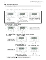
Page 37: ...TA character Press and hold Function Button for approximately 5 seconds to enter User Mode Power on the control panel must be on Customer can set the current time in J TA Turn the Dial Button clockwi...

Page 38: ...Press the Power Button OFF Display Screen will be blank 2 Press and hold the Function Button for approximately 5 seconds to get into the Installer Mode 3 1 EH oFF will appear on the Display Screen Ro...

Page 39: ...peration please check the neutralizer every few months for depletion Apply only corrosion resistant materials for the condensate drain lines such as 1 2 PVC CPVC Polypropylene pipe NOTICE Category IV...

Page 40: ...A 70 and or CSA C22 1 Electrical Code Part 1 in Canada ELECTRICAL SHOCK HAZARD For your safety turn off electrical power supply at service entrance panel before making any electrical connections to av...

Page 41: ...ings Maximum flame detecting voltage 2 4V Pre purge time Tp Maximum 10s minimum 1s Safety Time igniting time Ts 3 5s Igniting interval time 10s Post purge time Tip 60s Over heating 1 2 3 protection de...

Page 42: ...Page 42 4 20 Wiring Diagram...

Page 43: ...Page 43 4 21 Ladder Diagram...

Page 44: ...1 RS 485 RS485 SELV 5V 2 RS485 3 Unuse 4 RS485 5 RS485 CN4 1 FAN Unuse 2 GROUND SELV 30V 3 VDD SELV 14V 4 Fan power start coil SELV 30V 5 Fan power end coil 6 Fan speed feedback signal SELV 14V CN8 1...

Page 45: ...il Y Phase 4 5 GND 6 AGM Stepper Motor Position 7 VDD CN10 1 DHM Mixing Valve DHM Stepper motor coil Y phase SELV 14V 2 3 DHM Stepper motor coil X phase 4 5 GND 6 DHM Stepper motor position 7 VDD 8 VD...

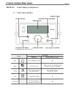
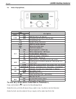
Page 46: ...Function Button Buttons Functionalities PRESS Tap PRESS and HOLD 5 seconds Power Turns Control Display ON OFF N A Modes Tap to return to menu If Display Power was On Status Display Mode If Display Pow...

Page 47: ...IRED HOT WATER TEMPERATURE 120 F Pump Operating Icon Example External Recirculation Icon Vacation Mode Icon Status Display Freeze Prevention Icon High Temperature Icon Temperature Unit Lock Mode PCB D...

Page 48: ...st and briefly show a sequence of diagnostic codes before entering into the Operating Mode It will then display the following information Indicate Example Target DHW Temperature If the flow is present...

Page 49: ...ter control valve position 0 Fully opened 100 Fully closed bYPS Water Mixing valve position 0 Fully opened 100 Fully closed I FC GAL Default Flow rate gpm Gallon min Temperature F Fahrenheit LIt Flow...

Page 50: ...tter Communication state indicate Current Time CAUTION Scalding Risk The use of an anti scald mixing valve at the hot water outlet water heater location can reduce potential for scalding Contact Manuf...

Page 51: ...Medium Lo Recirculation temperature Low 14 IV rIG Default 10 Pump ON time set 1 60 minutes POF Default 7 Pump OFF time set 1 30 minutes 15 HT HI 2 Burner ON by Hot Outlet temp High HI 1 Default Burner...

Page 52: ...Page 52 5 7 Error Mode Flashing Indicate Example Error Er xx will flash Installer icon NOTE When communication between the Control Display and the main controller is lost the will not be displayed...

Page 53: ...al operation 2 Check if DHW pipe is blocked Ensure there is enough water flowing to the water heater 3 Check DHW sensor at DHW outlet If resistance is zero replace the sensor 4 Check Operating Tempera...

Page 54: ...e Power button to clear the Error Code 1 Check APS and main controller connections Ensure all are secure 2 Check APS resistance If resistance is zero replace the air pressure switch 3 Check APS hose E...

Page 55: ...wer OFF and ON at the main power switch inside the water heater 2 Check wiring connections to supply water valve Ensure all are secure 3 Replace supply water valve Hard Lock 66 Mixing Valve Error Pres...

Page 56: ...or replace any damaged cables Soft Lock 79 Combustion Issues Cascade Common Vent Application NOTE This error will only appear in a cascaded and common vent system as Er 79 on the Master and Er 61 on...

Page 57: ...nd manifold gas pressures are in accordance with specifications Make sure that the water flow sensor with three wires has been properly connected on the main water valve Outlet water is too hot Make s...

Page 58: ...on control panel but water heater is oper ating Occurs when the communication is lost from the control to the display Check for loose connections and proper pin alignment engagement on the Control s...

Page 59: ...harness for loose connections and pin engagement at blower connections Water heater is in standby mode and fan is not running If FAN SPEED is not 0 RPM then replace the fan IGNITION FAULT Even if wat...

Page 60: ...caping it is a serious problem Call your qualified service technician for inspecting the Water Heater and condensate line Also refill the condensate trap if problem persists regularly Visually inspect...

Page 61: ...4 Dry the filter completely then reinsert the filter into the collar and secure with filter screws Cleaning cold water Inlet Filter Draining the Water Heater 1 Place a bucket under the appliance to c...

Page 62: ...ance procedures Every 6 Months Check piping gas and water Visually inspect for leaks around internal water piping Also inspect external water piping circulators relief valve and fittings Immediately c...

Page 63: ...s there space for a drain which is close to the Water Heater Are there any combustible materials near the Water Heater and vent pipe Is the air supply sufficient for proper operation of the Water Heat...

Page 64: ...relief valve at least 3 4 in diameter Have you installed the pressure relief valve on the hot water outlet pipe near the Water Heater Final check Burner flames The burner flame should be checked annua...

Page 65: ...repair iv charges to return the defective heater and or component part to the manufacturer WHAT IS THE PERIOD OF COVERAGE This limited warranty runs from date of installation or without proof of inst...

Page 66: ...his Limited Warranty Not Cover 2 Reimburse any costs associated with repair and or replacement 3 Replace and or repair any heater without complete model serial number 4 Replace any heater without prio...

Page 67: ...800 559 1583 Headquarters 20 Industrial Way Rochester NH USA 03867 603 335 6300 Fax 603 335 3355 9 Brigden Gate Halton Hills Ontario Canada L7G 0A3 905 203 0600 Fax 905 636 0666 www Laars com Litho in...

Page 68: ...905 203 0600 Fax 905 636 0666 www Laars com Litho in U S A Laars Heating Systems 22 07 Document 2192 Dimensions and specifications subject to change without notice in accordance with our policy of con...

Reviews: