LAARS Heating Systems
Page 22
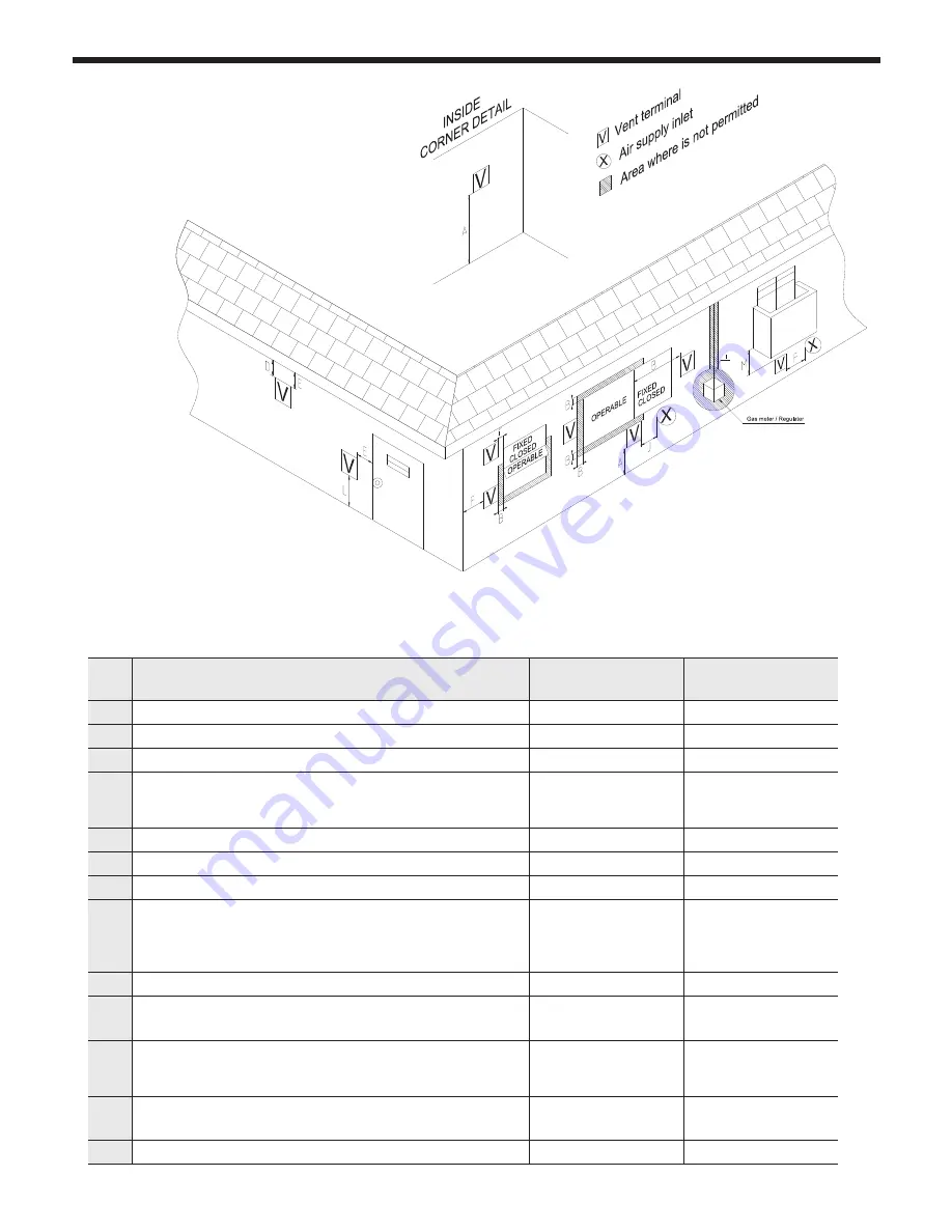
4.6 Locations for Vent Pipe Terminator
Description
US Direct Vent Instal-
lations
Canadian Direct Vent
Installations
A
Clearance above grade, veranda, porch, deck, or balcony
12 in (30 cm)
12 in (30 cm)
B
Clearance to window or door that may be opening
12 in (30 cm)
36 in (91 cm)
C
Clearance to permanently closed window
*
*
D
Vertical clearance to ventilated soffit located above the terminal
within
a horizontal distance of 2 feet from the center line of the terminal
*
*
E
Clearance to unventilated soffit
*
*
F
Clearance to outside corner
*
*
G
Clearance to inside corner
*
*
H
Clearance to each side of center line extended above meter/
regulator assembly
*
3 ft (91 cm) within a
height 15 ft (457 cm)
above the meter/
regulator assembly
I
Clearance to service regulator vent outlet
*
3 ft (91 cm)
J
Clearance to non-mechanical air supply inlet to building or the
combustion air inlet to any other appliance
12 in (30 cm)
36 in (91 cm)
K
Clearance to a mechanical air supply inlet
3 ft (91 cm) above if
within 10 ft (3 m) hori-
zontally
6 ft (1.83 m)
L
Clearance above paved sidewalk or paved driveway located on
public property
*
7 ft (2.13 m)
M
Clearance under veranda, porch, deck, or balcony
*
12 in (30 cm)
* For clearances not specified in ANSI Z224.1 / NFPA 54 or CAN/CSA-B 149.1, please use clearances in
accordance with local installation codes and the requirement of the gas supplier.
4.6.1 Direct Venting Clearances
Table 4. Direct Vent Clearances
SECTION 4. Installation
Summary of Contents for MFTCF140
Page 48: ...LAARS Heating Systems Page 46 4 19 Control Board Electrical Diagram SECTION 4 Installation...
Page 65: ...Mascot FT Floor Standing Combination Boiler Page 63 6 2 Fault Tree Analysis 1 Flame detection...
Page 75: ...Mascot FT Floor Standing Combination Boiler Page 73...
Page 78: ...LAARS Heating Systems Page 76 Heat Exchanger MFTCF140...

