LAARS Heating Systems
Page 36
Customer Service and Product Support:
800.900.9276 • Fax 800.559.1583
Headquarters:
20
Industrial Way, Rochester, NH 03867 • 603.335.6300 • Fax 603.335.3355
1869 Sismet Road, Mississauga, Ontario, Canada L4W 1W8 • 905.238.0100 • Fax 905.366.0130
www.Laars.com
Litho in U.S.A. © Laars Heating Systems 1607 Document 4290A
800.900.9276
•
Fax 800.559.1583
(Customer Service, Service Advisors)
20 Industrial Way, Rochester, NH 03867
•
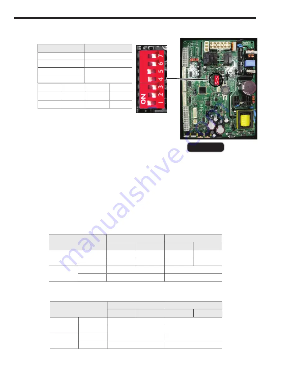
603.335.6300
•
Fax 603.335.3355
(Applications Engineering)
1869 Sismet Road, Mississauga, Ontario, Canada L4W 1W8
•
905.238.0100
•
Fax 905.366.0130
www.Laars.com
Document 4290A
M
ascot FT Floor-Standing Gas Conversion Kit
pg 3 of 4
Manifold pressure
‘NG’ type combustibility
‘LP’ type combustibility
2" VENT
3" VENT
2" VENT
3" VENT
MFTCF140
MAX Fire
-0.15
"
WC
-0.216
"
WC
-0.15
"
WC
-0.216
"
WC
MIN Fire
0
”
WC
0.002
”
WC
0.1
”
WC
0.079
”
WC
MFTCF199
MAX Fire
-0.134
”
WC
-0.173
”
WC
MIN Fire
-0.015
”
WC
-0.015
”
WC
Figure D
15.
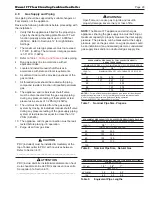
Setup your combustion analyser and place the sensor
into the combustion test port
16.
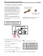
Per
Table B for Max Fire
,
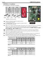
change dip switch 6 to ON and 7 to OFF.
The unit will cycle up to MAX fi re.
17.
WAIT for your combustion analyser to stabilize. This may take up to 3 minutes depending on your combustion
analyser. Then check the CO2
measurement for MAX fi re. Refer to Table D for acceptable MAX fi re
combustion readings. At this point, just record the CO2 readings at MAX Fire.
Do NOT attempt to adjust
CO2 at MAX Fire. ONLY in MIN Fire, so...
18.
Per
Table B for MIN Fire
,
change dip switch 6 to OFF and 7 to ON. The unit will cycle down to MIN Fire.
19.
WAIT for your combustion analyser to stabilize. Then check the CO2
measurement at MIN fi re. Refer to
Table D for acceptable MIN fi re combustion readings.
20.
If CO2
readings in Max Fire and MIN fi re are acceptable, then skip ahead to Step 23. If not, then open the
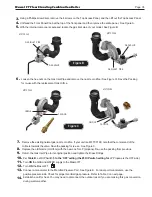
Gas Valve Adjustment Port by removing the cap screw with a 4mm Allen wrench. See Figure E.
21.
Then use the 4 mm Allen wrench to make a minor adjustment (1/8 turn) to either increase or decrease CO2.
Table B
DIP Switch Settings
MBH N/A 140 N/A 199
ON
OFF
MIN
Fire
Normal Operation
MAX
Fire
Normal Operation
NG Natural
LP Propane
3” Vent Size
2” Vent Size
ON
OFF
ON
ON
ON
OFF
OFF
ON
OFF
ON
ON
ON
DO
N
OT
C H
A N
G E
REFE
RENCE
ON
LY.
CO
2
value
‘NG’ type combustibility
‘LP’ type combustibility
2" VENT
3" VENT
2" VENT
3" VENT
MFTCF140
MAX Fire
8.5~10.5%
9.5~11 %
MIN Fire
8~10%
9~10.5 %
MFTCF199
MAX Fire
8.5~10.0%
9.5~11 %
MIN Fire
8~10%
9~10.5 %
Table C
Table D
4.13 Natural Gas to Propane Conversion
SECTION 4. Installation
Summary of Contents for MFTCF140
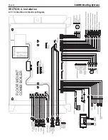
Page 48: ...LAARS Heating Systems Page 46 4 19 Control Board Electrical Diagram SECTION 4 Installation...
Page 65: ...Mascot FT Floor Standing Combination Boiler Page 63 6 2 Fault Tree Analysis 1 Flame detection...
Page 75: ...Mascot FT Floor Standing Combination Boiler Page 73...
Page 78: ...LAARS Heating Systems Page 76 Heat Exchanger MFTCF140...


