Mascot FT Floor Standing Combination Boiler
Page 39
4.14 Plumbing Guidelines
SECTION 4. Installation
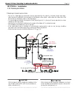
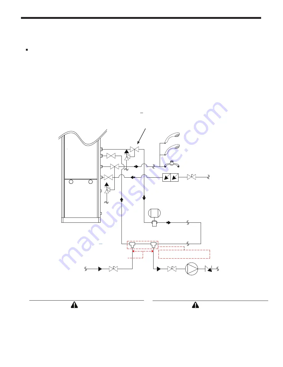
Diaphragm Type Expansion Tank
- The air in a diaphragm-type expansion tank is separated from the water by a flexible rubber membrane.
When the tank is installed in and connected to the piping of the system, water enters the other side of the
tank chamber and presses down on the diaphragm.
- You should always install an ‘Automatic Air Vent (Under figure ‘A’)’ on the top of the air separator to remove
residual air from the system.
- Automatic air vent has been installed on the inside of the Mascot FT combination boiler.
- The installation of additional air vent is optional.
- If the combination boiler is installed in a closed water supply system, such as one having a backflow
preventer in the cold water supply line, it will control thermal expansion.
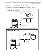
- Pump for primary loop is included with Mascot FT for < 15 ft.
Do not exceed 12" apart
PRIMARY LOOP
SECONDARY LOOP (SPACE HEATING)
(SPACE HEATING)
PRIMARY/SECONDARY
CONNECTION
1" PIPE
(CH SUPPLY)
1" PIPE
(CH RETURN)
3/4" PIPE
(DHW OUTLET)
Backflow preventer
3/4" PIPE
(DHW INLET)
Circulation pump
Check valve
Expansion tank
Air separator
(Closed type)
Pressure relief valve
Ball valve
Isolation valve
EXPANSION TANK
<
15 ft
- If
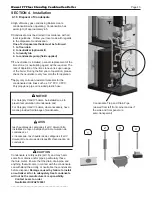
CAUTION
PRV (included) must be installed immediately at the
top of boiler outlet to PRV, with no valves between.
Refer to Section 4.15
__________________________________________
ATTENTION
PRV (inclus) doit être installé immédiatement en haut
de la chaudière sortie de PRV, sans les vannes entre.
Se reporter à la Section 4.15
__________________________________________
PRV
Summary of Contents for MFTCF140
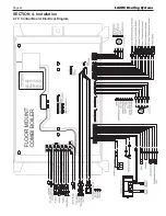
Page 48: ...LAARS Heating Systems Page 46 4 19 Control Board Electrical Diagram SECTION 4 Installation...
Page 65: ...Mascot FT Floor Standing Combination Boiler Page 63 6 2 Fault Tree Analysis 1 Flame detection...
Page 75: ...Mascot FT Floor Standing Combination Boiler Page 73...
Page 78: ...LAARS Heating Systems Page 76 Heat Exchanger MFTCF140...


