Mascot FT Floor Standing Combination Boiler
Page 47
4.20 Ladder Diagram
SECTION 4. Installation
EMI
FILTER
4
A
HOT
NEUTRAL
PWM
Driving Circuit
MCU
Relay 3
SMPS
Relay 4
Relay 5
Gas Sensor
AD Test
OP Water
TEMP
DHW_TEMP
Return _TEMP
Fire _SENSOR
Storage TEMP
Flow_SENSOR
High Limit
Primary
Secondary
Relay 3
Relay 4
Ignitor
Relay 5
Gas Valve
DC 14 V
DC 30V
DC 5V
F/B
FAN
Power Detector
Burner Limit
Speed Control
Fan RPM Sensor
DHM
Driving
circuit
Over Heat
TEMP
2
A
Pump1
Relay 1
Pump2
Relay 2
Relay 2
Relay 1
Water
Level
Sensor
Driver
Low level Sensor
Pump3
Relay 6
Power Display
Exhaust _TEMP
Villa GTX-920CP
Air Pressure Sensor
Heat Demand
Unuse(JUMP)
Unuse(JUMP)
DISPLAY CONTROL
External terminals
O/S
0-10V
Dry contact
input On/Off
External terminals
Summary of Contents for MFTCF140
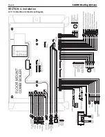
Page 48: ...LAARS Heating Systems Page 46 4 19 Control Board Electrical Diagram SECTION 4 Installation...
Page 65: ...Mascot FT Floor Standing Combination Boiler Page 63 6 2 Fault Tree Analysis 1 Flame detection...
Page 75: ...Mascot FT Floor Standing Combination Boiler Page 73...
Page 78: ...LAARS Heating Systems Page 76 Heat Exchanger MFTCF140...

