LAARS Heating Systems
Page 12
13.
Check gauge for correct water pressure and also
check water level in system. If the height
indicated above the boiler insures that water is at
the highest point in the circulating loop, then the
system is ready for operation.
14.
Within three (3) days of start-up, recheck all air
bleeders and expansion tank as described in
Steps 4 and 8 above.
SECTION 3.
Operation
3A. Controls - General
1.
Electronic Ignition Controls:
a.
Intermittent Ignition:
Pilots are automatically lit when the
operating aquastat calls for heat (System #4
and #9) The unit performs its own safety
check and opens the main valves only after
the pilot is proven to be lit. Whenever the
pilot flame is interrupted, the main gas
valve closes within 0.8 seconds.
b.
Electronically Supervised Standing Pilot
System (System #16):
When pilot flame fails, the ignition control
module responds in less than 0.8 seconds
and provides 100% safety shutdown.
2.
Operating Controls:
a.
Electrically Operating Controls:
Single, two-stage, four-stage or modulating
aquastats are provided in models HH and
PH boilers to control the desired service
water temperature. The temperature
sensing bulb is located in the boiler inlet.
b.
Modu-Snap Valves (Mechanical
Modulation Only):
These valves are furnished in addition to
the main electric gas valve. Each valve has
a remote capillary bulb immersed in a well
at the outlet header to maintain a constant
outlet temperature. Consult Table 5 for
desired temperature setting.
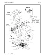
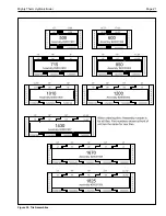
Figure 13. Typical Controls Locations.
Dial No.
1
2
3
4
5
6
7
8
9
Temp °F
120 135 150 165 180 195 210 225 240
Temp °C 49
57
66
74
82
91
99
107 116
Table 5. Modu-Snap Temperature Settings
3.
High Limit Controls:
The manual reset high limit switches are
provided as standard equipment on all
boilers. Automatic reset switches are
optionally provided. The temperature
sensing bulb of the switch is always located
in the boiler outlet. Burners will
automatically shut down whenever
overheating of water occurs.


