LAARS Heating Systems
Page 14
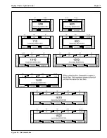
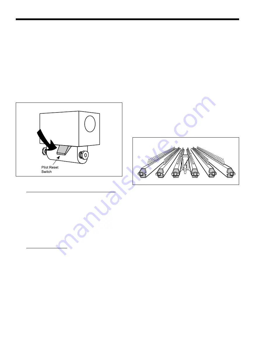
Figure 16. Main Burner Flame Pattern.
f.
Open manual pilot valve. Turn on main
electrical switch.
g.
Set temperature controller to desired
temperature. Pilot will light automatically
to ignite main burners whenever the
aquastat calls for heat.
h.
For standing pilot system, press on pilot
relay knob (see Figure 15), light pilot and
keep relay knob depressed for one minute
then release. Once the pilot is lit, the power
is supplied through the aquastat to the main
gas valve.
remove drain plug in the bottom of front header cover.
Drain every part of system subject to freezing
temperature.
SECTION 4.
Maintenance
1.
Lubricate the water circulating pump (see
instructions found on the pump).
2.
If a strainer is employed in a pressure reducing
valve or in piping, clean it every six (6) months.
3.
At start-up and every six (6) months thereafter,
the pilot and main burner flame should be
observed for proper performance (see Figure 16).
See attached lighting and shut-down instructions
for proper pilot flame pattern). If flame has the
appearance of “sooting” tips, check for debris
near orifices. Call serviceperson.
Figure 15. Pilot Safety Relay.
2.
To set the temperature and high-limit controls:
a.
Set the temperature controller at the system
design temperature.
b.
Set the high-limit to 40-50°F above
temperature controller setting.
c.
Models with Mechanical Modulation
Set the temperature controller (Modu-Snap
valve) dial to the desired water temperature
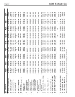
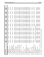
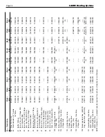
(see Table 5).
3.
Minimum input rates:
The low firing rate setting must be equal to or
greater than the specified minimum input rating
as shown on the appliance rating plate. Laars’
boilers use gas valves which are factory set to
provide an input on low fire that meet or exceed
the specified minimum.
3D. To Turn Off Boiler:
1.
Turn off main electric switch.
2.
Close all manual gas valves.
3E. To Shut Down System:
To shut down boiler, turn off all manual gas
valves and electrical disconnect switches. Whenever
danger of freezing exists, shut off water supply and
4.
Inspect the venting system for obstruction,
leakage and corrosion at least once each year.
5.
Keep boiler area clear and free from combustible
material, gasoline and other flammable vapors
and liquids (see Table 2 for minimum
clearances).
6.
Be certain all combustion air and ventilation
openings are unobstructed.
7.
Check for fouling on the external surfaces of the
heat exchanger every six months. (
NOTE
: After
installation and first start-up, check the heat
exchanger for fouling after the following periods
of operation: 24 hours, 7 days, 30 days, 90 days,
and once every six months thereafter).
Fouling on the external surfaces of the heat
exchanger is caused by incomplete combustion
and is a sign of combustion air and/or venting
problems. As soon as any fouling is observed,
the cause of the fouling should be corrected (see
Section 5, Troubleshooting Guide
). The heat
exchanger can be checked by locating a mirror
under the burners with a flashlight. An alternate
method is to remove the venting and top panel as
necessary to inspect from above. Also check the
vent system for defects at this time.


