Mighty Therm Hydronic Boiler
Page 9
other appliances remaining connected to the
common venting system are not in operation.
(a)
Seal any unused openings in the common
venting system.
(b)
Visually inspect the venting system for
proper size and horizontal pitch and
determine there is no blockage or
restriction, leakage, corrosion and other
deficiencies which could cause an unsafe
condition.
(c)
Insofar as is practical, close all building
doors and windows and all doors between
the space in which the appliances
remaining connected to the common
venting system are located and other spaces
of the building. Turn on clothes dryers and
any appliance not connected to the common
venting system. Turn on any exhaust fans,
such as range hoods and bathroom
exhausts, so they will operate at maximum
speed. Do not operate a summer exhaust
fan. Close fireplace dampers.
(d)
Place in operation the appliance being
inspected. Follow the lighting instructions.
Adjust thermostat so appliance will operate
continuously.
(e)
Test for spillage at the draft hood relief open-
ing after 5 minutes of main burner operation.
Use the flame of a match or candle, or smoke
from a cigarette, cigar or pipe.
(f)
After it has been determined that each
appliance remaining connected to the
common venting system properly vents
when tested as outlined above, return
doors, windows, exhaust fans, fireplace
dampers and any other gasburning
appliance to their previous conditions of
use.
(g)
Any improper operation of the common
venting system should be corrected so the
installation conforms with the latest edition
of the National Fuel Gas Code, ANSI
Z223.1. When resizing any portion of the
common venting system, the common
venting system should be resized to
approach the minimum size as determined
using the appropriate tables in Appendix G
in the National Fuel Gas Code,
ANSI Z223. 1.
2C. Installation of Outdoor Boilers
1.
Locate the boiler to provide the minimum
clearances as listed in Table 2, “Boiler
Clearances.” See Service Clearance, 2 B.1.
2.
Do not place the boiler in an enclosure or wall
recess. Avoid locations where wind deflection
off structures might cause a down draft. When
such wind conditions are possible, place the
boiler at least three (3) feet (0.9m) from the
structures.
3.
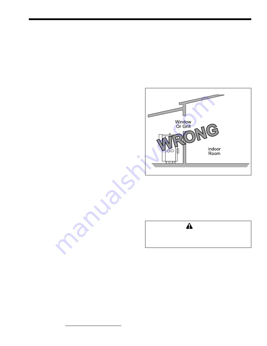
Never install the boiler under any kind of roof
overhang. Do not place the boiler below or
adjacent to any doors, windows, louvers, grills,
etc. which connect in any way with an inhabited
area of a building. This includes other structures
such as garages or utility rooms (see Figure 10).
Figure 10. Incorrect Outdoor Installation.
4.
Although these models are AGA designed
certified for outdoor installations, such
installations are not recommended in areas
where the danger of freezing exists unless proper
precautions are taken for freeze protection.
Caution
Outdoor installations are not recommended
in areas where the danger of
snow blockage exists.
2D. Gas Supply and Piping
Review the following instructions before
proceeding with the installation.
1.
Verify that the boiler is fitted for the proper type
of gas by checking the rating plate. Laars boilers
are normally equipped to operate below a 2000
foot (610m) altitude. Boilers equipped to operate
at higher altitudes have appropriate stickers or
tags attached.
2.
Use the figures in Table 4 to provide adequate
gas piping from the gas meter to the boiler.
3.
A trap (drip leg) must be provided ahead of the
gas controls (see Figure 11). A manual gas


