LAARS HEATING SYSTEMS
Page 8
Check heater wiring and pump for correct
voltage, frequency and phase. Consult the
National Electrical Code or the Canadian
Electrical Code regarding branch circuit
requirements for equipment with these motors.
2.
The heater should be wired exactly as shown in
the wiring diagram.
3.
All field installed electrical safety devices and all
field installed controllers (valve end switches,
draft switches, relays, timers) can be connected
to the heater control to the terminals shown in
the wiring diagram designated “Field Interlock.”
4.
Where the heater is installed with a draft fan
refer to the fan manufacturer's wiring diagram.
The draft switch should be wired across the field
interlock terminals in the heater control panel.
SECTION 3.
Water Piping Instruction
3.1 General Piping Practice
1.
Be sure to provide valves at the inlet and outlet
of the heater so it can be readily isolated for
service. A butterfly, ball type or similar type of
valve is recommended.
2.
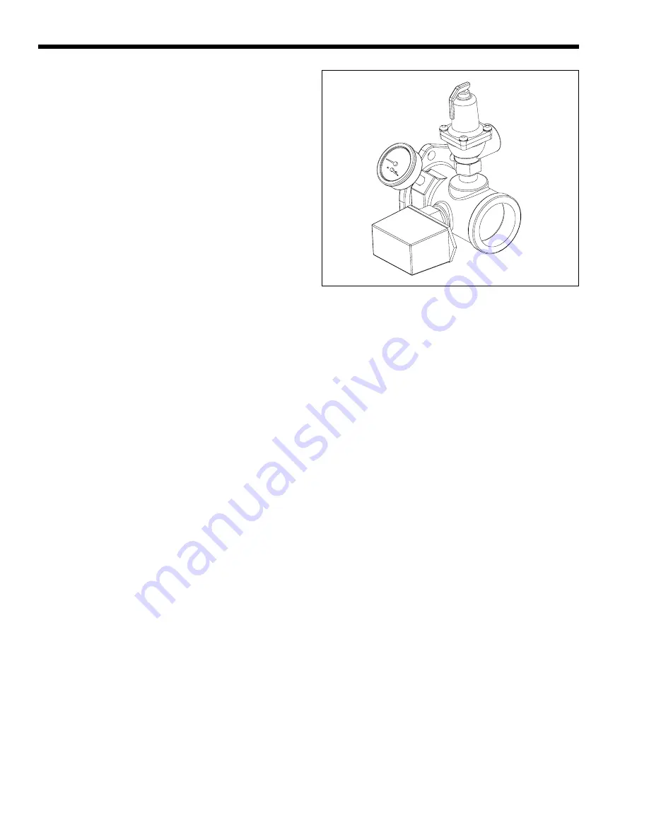
The pressure relief valve installed in the tapped
opening provided in the outlet header (see Figure
7), must be piped, but not fastened, to a drain or
floor sink. The drain pipe must be the same size
as the valve outlet and must pitch downward
from the valve. Pay special attention to relief
valve settings in installations where the heater is
located on the ground floor of a tall building, or
where the operating temperature of the heater is
above 210°F (99°C). In both instances, the static
pressure of the system is elevated and could
cause the relief valve to leak and bring
considerable raw water into the system.
3.
Where no special setting of the relief valve is
ordered, the factory will furnish a 75 psi setting
for heating boilers (PH models), and 125 psi for
water heaters (PW models).
4.
The pressure relief valve lever must be tripped at
least once a year to insure that waterways are
clean. When manually operating lever, water will
discharge through the drain line. Precautions
must be taken to avoid contact with hot water
and water damage.
3.2 Heating Boiler (PH Model)
3.2.1 Variable Water Flow System
Heating systems using zone valves, zone pumps
or 3-way valves can experience reduced water flow
Figure 7. Pressure Relief Valve Location.
through the boiler. This can result in an excessive
water temperature rise and unstable boiler operation. If
the system water flow is variable, the boiler's
temperature sensor must be installed in the outlet
water. Laars recommends primary-secondary pumping
for all variable flow systems (see Figure 9). Primary-
secondary pumping is mandatory for variable flow
systems. The boiler pump in a primary-secondary
system maintains constant flow through the boiler
even though the system flow is variable. In a primary-
secondary system the pressure drop of the boiler is not
added to the system.
3.2.2 System Pressure Requirements
The boilers are designed to operate on closed,
pressurized systems. Maintain a minimum of 12 psi
(81.8 kPa) on the system where boiler supply water
temperature is 200°F (93°C) or less. If higher
temperatures are required, the minimum system
pressure should be at least 15 psi (102.2 kPa) above
the water vapor pressure corresponding to the elevated
water temperature.
Heating boilers are not suitable for open systems
unless the supply water temperatures are kept below
180°F (82°C), and a minimum of 5 psi (34.1 kPa)
static head is maintained at the boiler.
3.2.3 Hot/Chilled Water Systems
When a boiler is connected to an air conditioning
system where the same water is used for heating and
cooling, you must prevent chilled water from entering
the boiler When changing such a system from cooling
to heating, allow the chilled water to circulate through
the building, after the chiller has been turned off, for a
period long enough for the water to warm up to at
least 105°F (41°C) before the water flows into the
boiler. It is equally important to prevent hot water
from entering the chiller. The system shown in


