Mini-Combo II
Page 5
2C. Piping
•
To Prevent damage to the unit, all soldering is to
be done prior to assembling the cold and hot
water, and any other connections to the tank.
•
Use suitable pipe dope or tape.
•
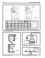
Before piping the boiler to the heating system,
be sure to install the system check valve
(provided with the unit) onto the inlet (return)
tee of the boiler with arrow pointed downward
(see Figure 3).
•
If anti-freeze is used in boiler system, local codes
may require a backflow preventer on cold supply
line. Use anti-freeze specifically intended for
hydronic heating system. Inhibited propylene
glycol is recommended.
WARNING
Do not use automotive or ethylene glycol anti-
freeze, or any undiluted anti-freeze. This can cause
severe personal injury, death or substantial property
damage.
If a backflow preventer, pressure reducing valve
or check valve is in cold water supply, install an
expansion tank on cold water supply line (Figure 4) to
prevent normal thermal expansion from repeatedly
forcing open the T&P relief valve.
T&P relief valves discharge piping must be
directed so that hot water flows away from all persons.
Attach run-off tube to T&P valve and run tube within
6" (152mm) from floor. No reducing couplings,
valves, or any other type of restriction is to be
installed in this line. This run-off tube must be
installed to allow free and complete drainage of both
valve and run-off tube.
Filling Storage Water Tank
1.
Open hot water faucet in house to allow air in the
tank and in piping to escape.
2.
Open shut-off valve(s) in cold water supply line.
3.
Open shut-off valve(s) in hot water supply line.
4.
When water discharges from the faucet, close it.
Check for system leaks and repair if necessary.
Filling and connecting boiler pipes:
Consult the JV boiler manual, Document 1025.
Caution
Never use water heater/boiler unless it is
completely filled with water.
2D. Wiring
Priority System: Under this wiring the storage
tank will be supplied before space heating. This will
insure that it gets adequate hot water flow from the
boiler to maintain a fully rated delivery of domestic
hot water.
Caution
In this priority mode, any demand for space heating
is postponed until the storage water tank has
reached set temperature. This delay in supplying
the space heating zones is usually not noticed by
the inhabitants of the living spaces. However, in the
event of certain storage water tank malfunctions,
space heating could be delayed indefinitely. If
undetected and uncorrected, freezing damage to
piping could result.
WARNING
Electrical shock can cause severe personal injury
or death. Disconnect power supply to the boiler
before doing any electrical work.
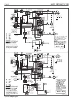
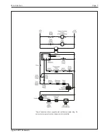
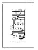
Electrical Connection: (See Figure 5, 6 and 7)
1.
Remove the two screws attaching the front cover
of the control box.
2.
There are five wires coiled in the area on the
right side of the control box, supplied with wire
nuts: 2 black wires twisted together, 2 white
wires twisted together, and a brown wire.
3.
Follow Figures 5, 6 and 7. Remove the wire nut
from the two black wires, and connect the hot
lead from a 115 volt power supply to both wires.
Secure the three wires with the wire nut.
4.
The two white, neutral wires should be joined to
the other neutral lead coming from the 115 volt
power supply, and the neutral lead coming from
the pump (space heating).
5.
The brown wire attaches to the hot side of the
space heating pump.
6.
There is a molex connector located on the left
side of the control panel. Connect the vent
damper harness to the molex connector and the
other end to the vent damper receptacle.
NOTE: The connection in step 6 should remain
intact at all times, otherwise the boiler will not fire.
Some Canadian units are supplied with vent
damper jumper plug. Do not remove jumper unless
vent damper is to be installed.


