background image

Page 18


LAARS Heating Systems

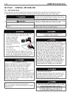
NOTE

: The boiler and all other gas 

appliances sharing the boiler gas supply 

line must be firing at maximum capacity to 

properly measure the inlet supply pressure. 

Low gas pressure could be an indication of 

an undersize gas meter and/or obstructed 

gas supply line.

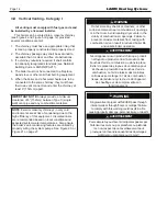
8.  The correct manifold gas pressure is stamped 

on the rating plate. The regulator is pre-set at 

the factory, and normally requires no further 

adjustment. 

9.  Before operating the boiler, the complete gas 

supply system and all connections must be 

tested for leaks using approved methods for the 

authority having jurisdiction. Do not use an open 

flame.

 CAUTION

Some leak test solutions (including soap and 

water) may cause corrosion or stress cracking. 

Rinse the piping with water after testing.

 ATTENTION

Certaines solultions d’essai d’étanchéité (y 

compris l’eau et le savon) peuvent causer de 

la corrosion ou de la fissuration. Rincez les 

tuyaux à l’eau apprès l’essai d’étanchéité.


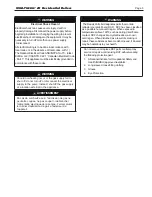
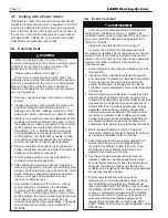
WARNING

The boiler is designed for use with either natural 

gas or LP gas, but only ships from the factory as 

natural gas. Conversion kits are available. 

DO 

NOT ATTEMPT TO CONVERT THIS HEATER 

FOR USE WITH ANY OTHER TYPE OF FUEL.


AVERTISSEMENT

Le unit est conçu pour être utilisé avec du gaz 

naturel ou du gaz LP, mais seulement des 

navires de l’usine comme gaz naturel. Des 

kits de conversion sont disponibles. 

NE PAS 

ESSAYER DE CONVERTIR CET APPAREIL À 

UN AUTRE TYPE DE GAZ.

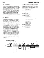
4.B  LP Gas Conversion

A conversion kit is available to convert this boiler for 

operation on LP Gas. The boiler’s existing gas valve 

is converted by changing the valve’s outlet regulator 

spring and resetting the outlet pressure regulator. 


See Section 12.C on page 50 for kit part numbers. 


The Gas Conversion Kit includes the following:
1. 

Gas valve regulator spring

2. 

Main Burner and Pilot Orifices

3. 

Installation Instructions

4. 

Conversion Label

4.C  Special Precautions for LP Gas

LP Gas is heavier than air and can therefore more 

readily collect or “pool” in enclosed areas if provision 

for proper ventilation is not made. Be sure to pay 

special attention to proper ventilation for LP gas. 

Locate boilers a safe distance from LP gas cylinders 

and filling equipment. In the United States, consult 

the “National Fuel Gas Code” ( NFPA 54 / ANSI 

Z223.1, latest edition ) or in Canada, the Propane 

Installation Code ( CSA-B149.2 ), any local codes and 

fire protection authorities about specific installation 

restrictions in your area.

Summary of Contents for MINI-THERM JX Series

Page 1: ...tment Installation and service must be performed by a qualified installer service agency or gas supplier AVERTISSEMENT Assurez vous de bien suivres les instructions donn es dans cette notice pour r du...

Page 2: ...0V 23 7 C Outdoor Sensor 23 7 D Field Connections 24 7 D 1 TB1 Term Block 1 TT DHW OAS 24 7 D 1 a TT Central Heat 24 7 D 1 b DHW 24 7 D 1 c Field Interlocks 24 7 D 1 d PV Terminals 24 7 D 1 e WWSD COM...

Page 3: ...MAINTENANCE 10 A Removing the covers and panels 40 10 A 1 Access Cover Removal 40 10 A 2 Flue Collector Access 40 10 A 3 Side Panel Removal 41 10 A 4 Draft Hood Removal 41 10 B Maintenance 42 SECTION...

Page 4: ...adjust the outlet control limit or use temperature limiting valves to obtain a maximum water temperature of 125 F 52 C WARNING The inlet gas pressure to the unit must not exceed 13 W C 3 2kPa WARNING...

Page 5: ...mperatures above 180 F such as during direct ame contact RCF changes into crystalline silica a known carcinogen When disturbed as a result of servicing or repair these substances become airborne and i...

Page 6: ...all packages listed on the packing slip Inspect everything for damage immediately upon delivery and advise the carrier of any shortages or damage Any such claims should be filed with the carrier The...

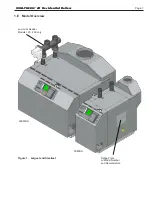
Page 7: ...Page 7 Figure 1 Largest and Smallest 200 MBH Rating Plate w Model Number and Nomenclature Low Loss Header Models 125 200 only 50 MBH 1 E Model Overview MINI THERM JX Residential Boilers...

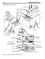
Page 8: ...ply Main Power 120V Connections See 7 B on page 23 See 7 D on page 24 Gas Valve Pilot Ignitor Sensor Shown with front cover off Field Connections TB1 DHW Relay Connections TB3 Field Connections TB2 Lo...

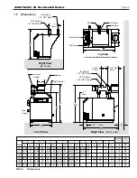
Page 9: ...5 8 73 31 79 7 18 1 1 4 3 4 Front View Draft Diverter Damper 6 3 1 4 8 3cm Low Loss Gas Supply Header A D B V V 1 1 4 NPT Female OUT Supply IN Return 1 1 4 NPT Female 53cm 23cm F2 11 8cm 4 5 8 21 9 1...

Page 10: ...s can be installed in a closet as long as all minimum clearances are followed including between the front of the boiler and the closet door when it is closed See Figure 3 Consult the American National...

Page 11: ...es Improper venting of this appliance can result in excessive levels of carbon monoxide which can result in severe personal injury or death AVERTISSEMENT Cette chaudi re doit tre ventil conform ment a...

Page 12: ...wo permanent air supply openings one within 12 inches 305mm of the ceiling the other within 12 inches 305mm of the floor NOTE In Canada follow Canadian Standard CAN CGA B149 or local codes Outside Air...

Page 13: ...t on the boiler The boiler top is designed so that it can be easily removed for normal boiler service and inspection without removal of the venting Avoid terminating boiler vents near air conditioning...

Page 14: ...al conditions and expected system water temperatures Also ensure the boiler s anti condensing features are utilized by properly wiring the system pumps See Figure 20 or Figure 21 on page 27 WARNING Do...

Page 15: ...5 See Note 5 See Note 5 r e n r o c e d i s n i o t e c n a r a e l C G H Clearance to each side of centerline extended above meter regulator assy 3 ft 91 cm within a height of 15 ft 4 6 m m c 1 9 t f...

Page 16: ...tional Fuel Gas Code ANSI Z223 1 NFPA 54 AVERTISSEMENT Lorsqu une chaudi re existante est retir e d un syst me de ventilation commun le syst me de ventilation commun est susceptible d tre trop grand p...

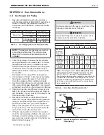
Page 17: ...d pipe between the meter and the boiler a restrictive fitting or an undersized gas meter Gas supply pressures to the heater are listed in Table 3 on page 17 SECTION 4 Gas Connections 4 A Gas Supply an...

Page 18: ...ATTEMPT TO CONVERT THIS HEATER FOR USE WITH ANY OTHER TYPE OF FUEL AVERTISSEMENT Le unit est con u pour tre utilis avec du gaz naturel ou du gaz LP mais seulement des navires de l usine comme gaz nat...

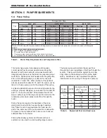
Page 19: ...able 6 Equivalent Feet and Head Loss Model Size GPM Equivalent Feet of Type M Copper Feet of Head Loss 50 5 75 4 9 100 6 5 75 7 5 75 10 3 100 13 8 100 10 75 17 6 100 23 5 MINI THERM JX Residential Boi...

Page 20: ...ow Loss Header with its integral Boiler Pump eliminates the need for by pass piping because it allows the system flow and the boiler flow to be independent of each other without the cost and complexit...

Page 21: ...es Valves Indirect Tank Air Scoop Pump Zone Pumps mustbesized properly Valves Check Valves Check Valve Valves Indirect Tank Pump Check Valve Valves Indirect Tank Pump JX JX JX JX Check Valve Valves Va...

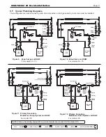
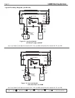
Page 22: ...and 100 Low Loss Header is standard on models 125 150 and 200 and Optional for models 50 75 and 100 Figure 13 Low Loss Header with Zone Pumps and DHW Typical Plumbing Diagrams continued KEY PUMP CHECK...

Page 23: ...No attempt should be made to connect electrical wires to any other location except the terminal blocks and line voltage hanging leads pigtail 7 B Main Power 120V Main Power Connection This boiler has...

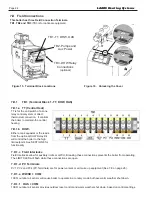
Page 24: ...l Block Locations TB3 DHW Relay Connections optional TB2 Pumps and Aux Power TB1 TT DHW OAS 7 D 1 c Field Interlocks Field Interlocks allow for auxiliary limits or LWCO Breaking these connections prev...

Page 25: ...ts high enough supply water temperature the system pump will be enegized This feature helps protect the boiler from condensation due to low inlet water temperature 7 D 2 c Aux Power This terminal and...

Page 26: ...rs Power Vent Kit L1 N T1 T2 T3 L1 N T1 T2 T3 L N 1 2 4 Example Fields Controls CAS 4 Wiring to JX Combustion Air System Example Laars Power Vent Kit and Fields Controls CAS 4 Wiring to JX Combustion...

Page 27: ...ave a dedicated boiler pump such as LLH when using this method L N 1 2 4 Laars Power Vent Kit Example Typical Zone Pump Control Wiring to JX for Anti condensing protection Example Typical Zone Valve C...

Page 28: ...LD DHW TT Boiler Controller O Y R P O O 24V L PILOT VALVE 24V L MAIN VALVE 24V N Y GAS VALVE S BLOCKED VENT SWITCH SWITCH ROLL OUT 24VAC 120VAC R O A A OAS COM W W SD X1 X2 X4 Y Y R R CONNECTOR DAMPER...

Page 29: ...R PUMP N 120VAC SYS PUMP X2 4 PILOT VALVE X1 2 X1 8 X1 5 MAIN VALVE 24V N 24V L 24V L SPARK IGNITOR GENERATOR SPARK J1 WATER TEMP SENSOR FACTORY INSTALLED X3 5 POWER VENTER PROOF OF FAN not supplied F...

Page 30: ...ory set at 190 F To adjust turn the HI TEMP dial until the desired setting is displayed Range 160 220 F 8 A 3 Low Limit Advanced Options Adjust Low Limit is not applicable to the JX but this knob does...

Page 31: ...low the high limit setting to maximize fuel efficiency When the boiler water reaches the target temperature the LED illuminates and the burner will shut down The boiler water will continue to circulat...

Page 32: ...TING BUTTON and simultaneously adjust the ECONOMY dial to the desired setting To turn the feature off which will allow space heating regardless of outdoor temperature press and hold the TEST SETTING B...

Page 33: ...l boost feature If the thermostat is not satisfied thirty minutes after the boiler reaches the reset temperature the control will boost the reset temperature by 10 degrees It will continue to boost at...

Page 34: ...operation WARNING DO NOT ADD WATER UNTIL THE BOILER HAS FULLY COOLED To activate Manual Reset LWCO mode 1 Turn the LO TEMP dial to access the Program Mode indicated in the display as Pro 2 Turn the H...

Page 35: ...nstalled with a Electro Well for low water cut off functionality To View Current Settings Press and release the Test Settings Button in short intervals to sequentially display the following settings H...

Page 36: ...P Carbon monoxide hazard The vent damper must be fully open and the flue must be clear before the main burner fires If the burner fires when the vent damper is not fully open or the flue is blocked da...

Page 37: ...flame is observed then re tighten its associated locking screw Factory setting is 75 from shutter to burner orifice mounting plate Use the Mini Gauge to set to factory starting point See Figure 29 and...

Page 38: ...pilot should be adjusted down using the valve s pilot adjustment screw shown in Figure 31 If the flame is small and the inner cone does not engulf the pilot ignitor sensor then the pilot is under fir...

Page 39: ...s d une montre pour le mettre en position de marche ON 8 R glez le thermostat la temp rature d sir e 9 Mettez l appareil sous tension 10 Si l appareil ne se met pas en marche suivez les instructions i...

Page 40: ...ratures could cause a hazardous condition 10 A 1 Access Cover Removal To remove the front access cover simply turn the lock at the top center of the panel with a flat screw driver slot indicates locki...

Page 41: ...l 10 A 3 Side Panel Removal Remove the front access and the top as described previously Drain the boiler and remove the drain valve and or the PRV and associated fittings depending on the panel being...

Page 42: ...erved If the flame has the appearance of sooting tips check for debris near the orifices Clean any debris from orifice area and remove burners to ensure they are debris free inside and out If this doe...

Page 43: ...form 24 VAC voltage checks attach one meter lead to terminal 7 of TB1 Use the other lead to check for power on any switch on the boiler 5 To perform voltage checks on 120VAC attach one meter lead to e...

Page 44: ...ace heat exchanger 6 Pump noisy Air in volute Bleed air from volute Check pump alignment Worn bearings Replace worn parts 7 Boiler pounding or knocking Too low water flow through boiler Check temperat...

Page 45: ...Boiler has Reached the Target Temperature When the ECONOMY function is active the control monitors heating demand and establishes Target boiler temperatures below the high limit setting to conserve fu...

Page 46: ...COOL BEFORE ADDING WATER Recheck wiring Burner should never fire when red or yellow LED are lit Is either Yellow LED On The Control has Reached Target or High Limit Temperature The Control is Operatin...

Page 47: ...3 A4 A12 A13 A14 D3 B2 B4 B5 C6 B6 D13 D2 B8 B9 A15 D1 A6 A5 A16 A17 B1 B7 C1 D4 C5 C4 B4 B3 SECTION 12 REPLACEMENT PARTS Reference to 12 B Parts List starting on next page 12 A Parts Illustrations MI...

Page 48: ...shown 1 C2018100 BAG POLY RECLOSABLE 2x2 not shown 1 H2413100 INSTRUCTIONS INSTALLATION DHW RELAY KIT JX nolt sh 1 5X7002 DHW PANEL ASSY JX ECN DECIMALS XX DRAFT CHECK RELEASE REVISIONS KAG 6JUL REV C...

Page 49: ...43 A3 Panel Front 5X3038 7X3038 10X3038 12X3038 15X3038 20X3038 A4 Front Cover R5X3045 R7X3045 R10X3045 R12X3045 R15X3045 R20X3045 A5 Latch Slot Quarter Turn Assy R2086800 R2086800 R2086800 R2086800 R...

Page 50: ...embly Natural R0061600 R0061600 R0061600 R0061600 R0061600 R0061600 Pilot orifice LP W2001700 W2001700 W2001700 W2001700 W2001700 W2001700 C2 Main Gas Valves Gas Valve Natural V2029300 V2029300 V20293...

Page 51: ...dependent of system flow so that Primary Secondary system piping is unnecessary and system piping is simplified Primary Secondary Piping Two or more interconnecting circulating loops each with its own...

Page 52: ...6 Fax 800 559 1583 Headquarters 20 Industrial Way Rochester NH USA 03867 603 335 6300 Fax 603 335 3355 9 Brigden Gate Halton Hills Ontario Canada L7G 0A3 905 203 0600 Fax 905 636 0666 www Laars com Li...

Reviews: