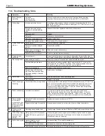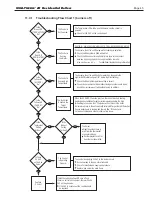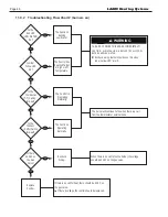
Page 31
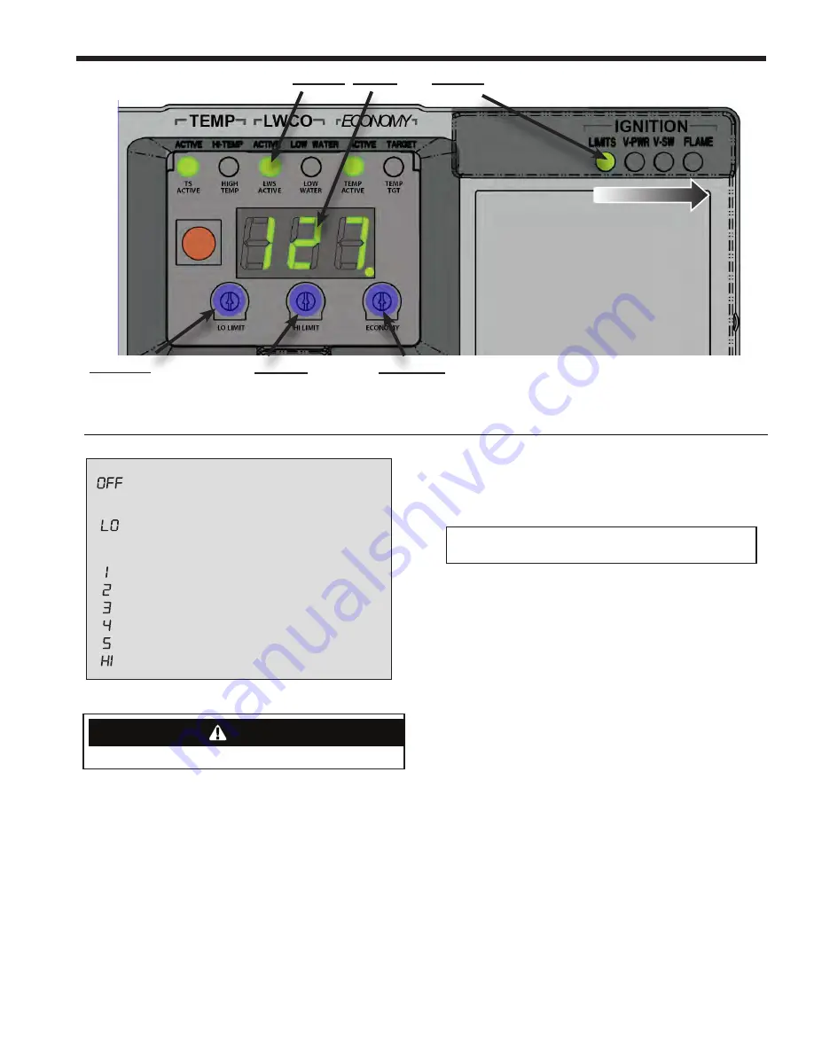
Economy
(Zone Adjust)
Hi Limit
(High Temp)
Lo Limit
(Adv Options / Adj)
Control,
Digital
and
Ignition
LEDs
TS
ACTIVE
HIGH
TEMP
LWS
ACTIVE
LOW
WATER
TEMP
ACTIVE
TEMP
TGT
LO LIMIT
HI LIMIT
ECONOMY
4
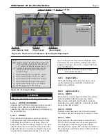
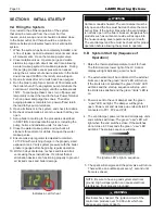
NOTE: Settings can be checked using the
TEST/SETTINGS Button. See page 7 for details.
Setting the High Limit
The high limit is factory set at 190°F. To adjust, turn the HI
TEMP Dial
until the desired setting is displayed. (Setting
range: 100°-220°F)
Setting the Low Limit
The low limit is designed to maintain temperature in boilers
equipped with tankless coils used for domestic hot water. The
low limit is factory set to OFF. Prior to adjusting, remove the
jumper (not equipped on all units)
. Then turn the LO TEMP
Dial
clockwise until the desired temperature is displayed.
For proper operation, the low temperature limit setting should
be at least 10° below the high limit setting.
NOTE: For cold
start operation, the low limit must be turned OFF.
IMPOR-
TANT: If low limit temperature cannot be set above 140°F, re-
move jumper
. (Setting range: OFF or 110°-220°F).
Setting the Economy Feature
The Economy Feature is factory set for a 1 zone heating sys-
tem. To adjust, turn the ECONOMY Dial
until the number
displayed equals the number of heating zones.
Do not include
indirect water heaters in the number of heating zones.
The
Economy Feature conserves fuel by reducing boiler tempera-
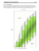
ture (see “How Thermal Targeting Works” on page 6). If the
heating system is unable to supply needed heat to the house,
the ECONOMY Dial should be turned to a lower setting (ex-
ample: In a three zone house, turn the dial to 2 or 1). Con-
versely, if the boiler provides adequate heat, added fuel
savings can be achieved by selecting a higher setting (exam-
ple: 4 or 5). If the heating and indirect water heater signals
were not separated when wiring the control, the Economy
Feature should be turned OFF to ensure the boiler supplies
adequate temperature to heat the indirect tank.
SETTING THE CONTROL
High Temperature
Limit Setting
(160°-220°F)
Factory: 190°F
Control LEDs
Ignition LEDs
(OFF or LO, 1, 2, 3, 4, 5, HI)
Factory: 1
SETTING
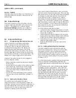
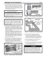
Disables economy function. Will allow boiler to fire
until hi-limit temp is reached and will re-fire with
a 30° subtractive differential
(adjustable from 10°-30°).
Provides lowest level of fuel savings. Use this
setting only if the house does not stay warm
Recommended setting for single zone systems
Recommended setting for Two zone systems
Recommended setting for Three zone systems
Recommended setting for Four zone systems
Recommended setting for Five zone systems
Provides highest level of fuel savings
Indicator Light
(announces heat call)
Test/Settings Button
Dynamic Display
Water Temperature
and Real Time
Verification of Setting
Adjustments.
Differentials are automatic
and will vary based on
control settings and boiler
temperature.
Note: The high limit differential
Low Limit
High Limit
Economy
can be adjusted when the econ-
omy feature is turned off. See
Optional Features on page 9.
*Model specific
at higher settings.
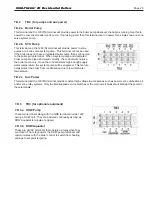
Figure 25. The Dials and Indicators of the Digital Dashboard
Figure 26. Economy Settings
WARNING
Allow the boiler to fully cool before adding water.
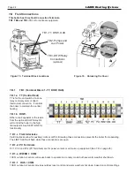
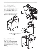
8.A.4.e ACTIVE (ECONOMY)
Indicates that the Thermal Targeting function is active
and the control will reduce boiler temperature to
conserve fuel. The Economy feature is activated using
the ECONOMY dial.
8.A.4.f TARGET
When the Economy feature is active, the control
continually sets target temperatures below the high
limit setting to maximize fuel efficiency. When the
boiler water reaches the target temperature, the LED
illuminates and the burner will shut down. The boiler
water will continue to circulate and heat the house as
long as the thermostat call continues. The LED will
8.A.5 Digital LEDs
The Digital Display will present the numeric value
of all temperatures and setpoints and advanced
programming settings.
8.A.6 Ignition LEDs
8.A.6.a LIMITS
Illuminates on a call for heat to indicate the external
limits are satisfied. External limits may include
flame rollout, spill switch, field interlock terminals
(secondary low water cutoff etc). If the external limits
are open the LED will blink.
8.A.6.b V-PWR
Indicates power has been sent to the vent damper.
The damper will open causing it’s end switch to close.
8.A.6.c V-SW
Illuminates when the vent damper end switch and
PV1 and PV4 terminals (such as power venter and/
or air makeup air pressure switch) have closed
indicating the flue is clear. If the damper end switch or
the air pressure switch fail to close in 30 seconds the
LED will blink.
SYSTEM START-UP
1
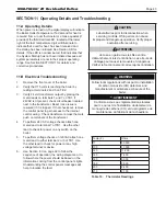
Carbon monoxide hazard. The vent damper must be fully open and the flue must be clear
before the main burner fires. If the burner fires when the vent damper is not fully open or the
flue is blocked, dangerous flue products such as carbon monoxide will escape into the house
causing severe personal injury or death. The vent damper and flue must be checked for
proper operation before allowing the system to operate.
Electrical shock hazard. The ignition circuit of the control can produce over 10,000 volts
which can cause severe injury or death.
Decimal lights on a call for heat.
LEDs light in sequence.
The Ignition LED’s
light in sequence
stay lit until the boiler temperature drops below the
differential set point at which point the boiler will be
allowed to fire again. See 8.C.5 on page 34 for how
to set the differential.
NOTE: This LED illuminates regularly during
normal boiler operation.
M
INI-
T
HERM
JX
Residential Boilers
®

