Page 8
Dimensional
Data
1-1/4” NPT Female
OUT (Supply)
IN (Return)
1-1/4” NPT Female
53cm
23cm
F2
11.8cm
4-5/8"
21"
9-1/8" Max
E
Right View
(125, 150, 200)
OUT (Supply)
IN (Return)
1-1/4” NPT Male
1-1/4” NPT Male
F1
7"
18cm
Right View
(50, 75, 100)
In Return
Top View
Low Loss Header & Damper not shown
Pressure Gauge
Control Display
PRV
Out Supply
C
WATER
CONN
GAS
CONN
SIZE
A
B
C
D
E
V
F2
F1
in.
cm
in,
cm
in.
cm
in,
cm
in.
cm
in.
cm
in.
cm
in.
(inches)
(inches)
cm
50 11-3/4 30 31-5/8 80 25-1/8 64 24-3/4 63 27-5/8 70 24-7/8 63
-
-
4
10
1-1/4
3/4
75 14-1/2 37 31-5/8 80 25-5/8 65 24-3/4 63 28-5/8 73 24-7/8 63
24-7/8 63
-
-
-
-
5
13
1-1/4
3/4
100 17-3/8 45 32-1/8 82 25-1/2 65 25-3/8 65 28-5/8 73
5
13
1-1/4
3/4
125 20-1/8 52 32-1/8 82
25
64 25-3/8 65 28-5/8 73
-
-
31
79
6
15
1-1/4
3/4
150
23
59 32-1/8 82
25
64 25-3/8 65 28-5/8 73
-
-
31
79
6
15
1-1/4
3/4
200 28-3/8 73 32-1/4 82 24-5/8 63 26-1/4 67 28-5/8 73
-
-
31
79
7
18
1-1/4
3/4
Front View
Draft Diverter
Damper
6”
15.3cm
3-1/4” 8.3cm
Low Loss
Gas
Supply
Header
A
D
B
V
1-1/4” NPT Female
OUT (Supply)
IN (Return)
1-1/4” NPT Female
53cm
23cm
F2
11.8cm
4-5/8"
21"
9-1/8" Max
E
Right View
(125, 150, 200)
OUT (Supply)
IN (Return)
1-1/4” NPT Male
1-1/4” NPT Male
F1
7"
18cm
Right View
(50, 75, 100)
In Return
Top View
Low Loss Header & Damper not shown
Pressure Gauge
Control Display
PRV
Out Supply
C
WATER
CONN
GAS
CONN
SIZE
A
B
C
D
E
V
F2
F1
in.
cm
in,
cm
in.
cm
in,
cm
in.
cm
in.
cm
in.
cm
in.
(inches)
(inches)
cm
50 11-3/4 30 31-5/8 80 25-1/8 64 24-3/4 63 27-5/8 70 24-7/8 63
-
-
4
10
1-1/4
3/4
75 14-1/2 37 31-5/8 80 25-5/8 65 24-3/4 63 28-5/8 73 24-7/8 63
24-7/8 63
-
-
-
-
5
13
1-1/4
3/4
100 17-3/8 45 32-1/8 82 25-1/2 65 25-3/8 65 28-5/8 73
5
13
1-1/4
3/4
125 20-1/8 52 32-1/8 82
25
64 25-3/8 65 28-5/8 73
-
-
31
79
6
15
1-1/4
3/4
150
23
59 32-1/8 82
25
64 25-3/8 65 28-5/8 73
-
-
31
79
6
15
1-1/4
3/4
200 28-3/8 73 32-1/4 82 24-5/8 63 26-1/4 67 28-5/8 73
-
-
31
79
7
18
1-1/4
3/4
Front View
Draft Diverter
Damper
6”
15.3cm
3-1/4” 8.3cm
Low Loss
Gas
Supply
Header
A
D
B
V
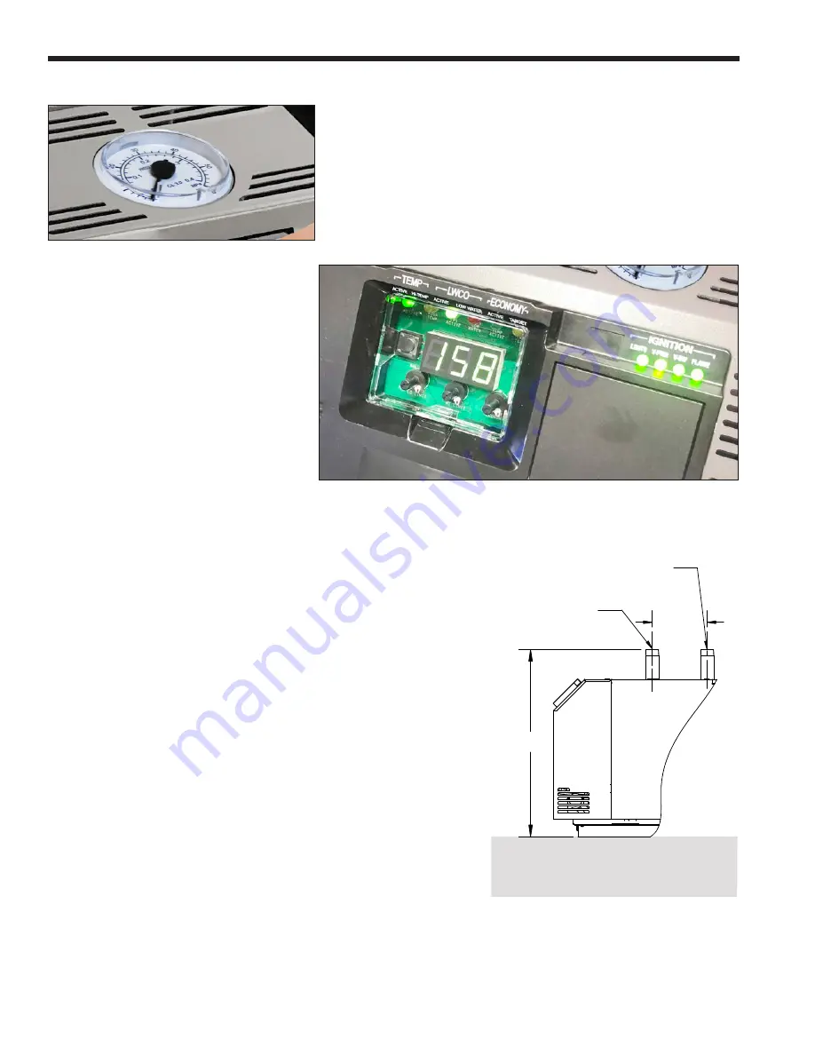
The Pressure gauge is installed just above the Digital
Dashboard. The pressure is sensed at the top front
section of the inlet/outlet header.
The Digital Dashboard displays the boiler's
status while it is running. The dials and
the mode button are underneath the
removable transparent cover and allow for
advanced settings and installations that
have outdoor reset and Low Water Cut Off
(LWCO) with manual reset and several
other advanced settings. See SECTION 8
on page 30.
Figure 4. System Pressure
Figure 5.
Boiler Status
1.F Pressure Gauge
1.G Digital Dashboard
1.H
The Installation Kit
This residential unit is shipped in a single crate
with a boxed installation kit that contains these
components.
1. I/O Manual
2. Vent Damper
3. Burner Air Shutter Gauge (Mini Gauge)
1.I
Accessory Kits Available
See Section 12.B on page 50 for part numbers.
•
Low Loss Header with Integral Pump for 50 - 100
(Standard on larger models)
•
Conversion kits for LP and altitude are available
from 0 to 10,000’ both fuels.
•
Domestic Hot Water Pump Relay Kit
•
Power Vent Kits
•
Outdoor Air Sensor
1.J Dimensions
LAARS Heating Systems


