49
Service Manual - NeoTherm 500
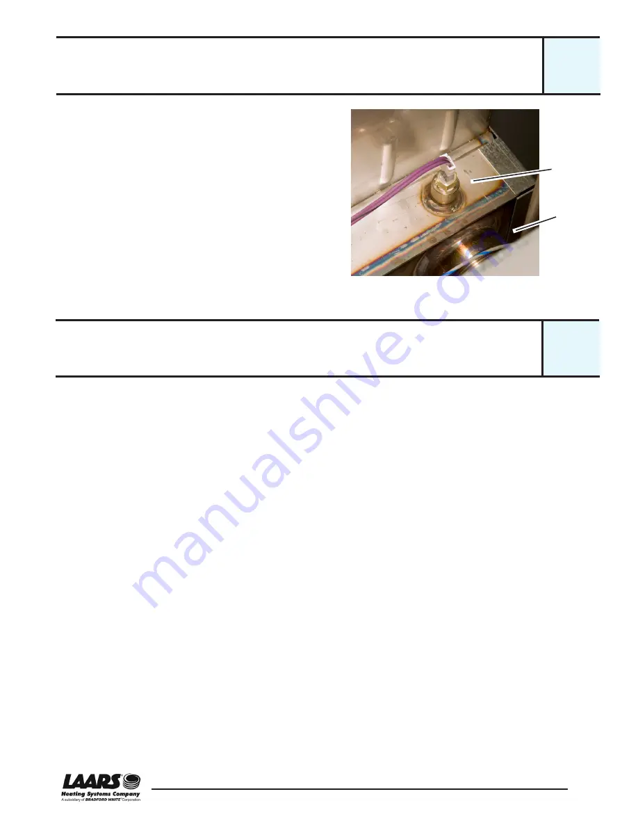
A typical installation for the inlet water temperature
sensor is shown in Fig. B28-1. The sensor is connected
to J8 4-5 on the control module. This sensor uses an
electronic device called a “thermistor.” For instructions
on testing the sensor, see Section B32.
To reset the control system after the inlet sensor trips:
• On a unit with the original (white) user interface -
Press the Reset button near the lower left-hand
corner of the display. This will reset the lockout, and
the lockout code will disappear.
• On a unit with current user interface -
Reset by pressing the OK button.
Removing and Replacing the Inlet Water Temperature Sensor
The inlet water temperature sensor allows the control system to monitor the
temperature of the water as it returns to the NT unit.
Tools and equipment required:
• Crescent wrench or 14 mm socket
• Pipe dope or Teflon® tape
Procedure:
1. Turn off power to the system. Use the main disconnect switch mounted
above the front panel.
2. Isolate the boiler. Turn off the water shutoff valves located upstream and
downstream of the unit.
3. Drain the boiler. The drain valve is located near the lower end of the heat
exchanger.
4. The inlet water temperature sensor is mounted in the shoulder of the
heat exchanger assembly, just above the point where the water inlet pipe
is attached to the heat exchanger. (The inlet pipe is marked with a label
on top of the unit.) Remove the top panels on the unit so you can reach
the temperature sensor.
5. Unplug the wiring connector (two wires). The connector is locked in
place by a “squeeze tab.” Press on the tab to release the connector.
6. Unscrew the sensor using the 14 mm socket or a crescent wrench. Turn
counter-clockwise to unscrew the part.
7. To reassemble, reverse the process we have just described. Be sure to
use pipe dope or Teflon® tape on the threaded part of the sensor.
Sensor
Water
inlet
pipe
Fig. B28-1 - Inlet water temperature sensor (typical)
B28
Inlet Water Temperature Sensor
B29
Summary of Contents for NeoThem NTH
Page 2: ......
Page 10: ...Service Manual NeoTherm 500 viii ...
Page 68: ...58 Service Manual NeoTherm 500 ...
Page 115: ...105 Service Manual NeoTherm 500 Appendix 3 Wiring Diagram App3 ...
Page 116: ...106 Service Manual NeoTherm 500 ...
Page 117: ......


