Page 14
For Water Connection Pipe Sizes, See “Table 15.
Water Connection Pipe Sizes” on page 34
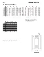
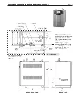
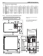
Table 1.
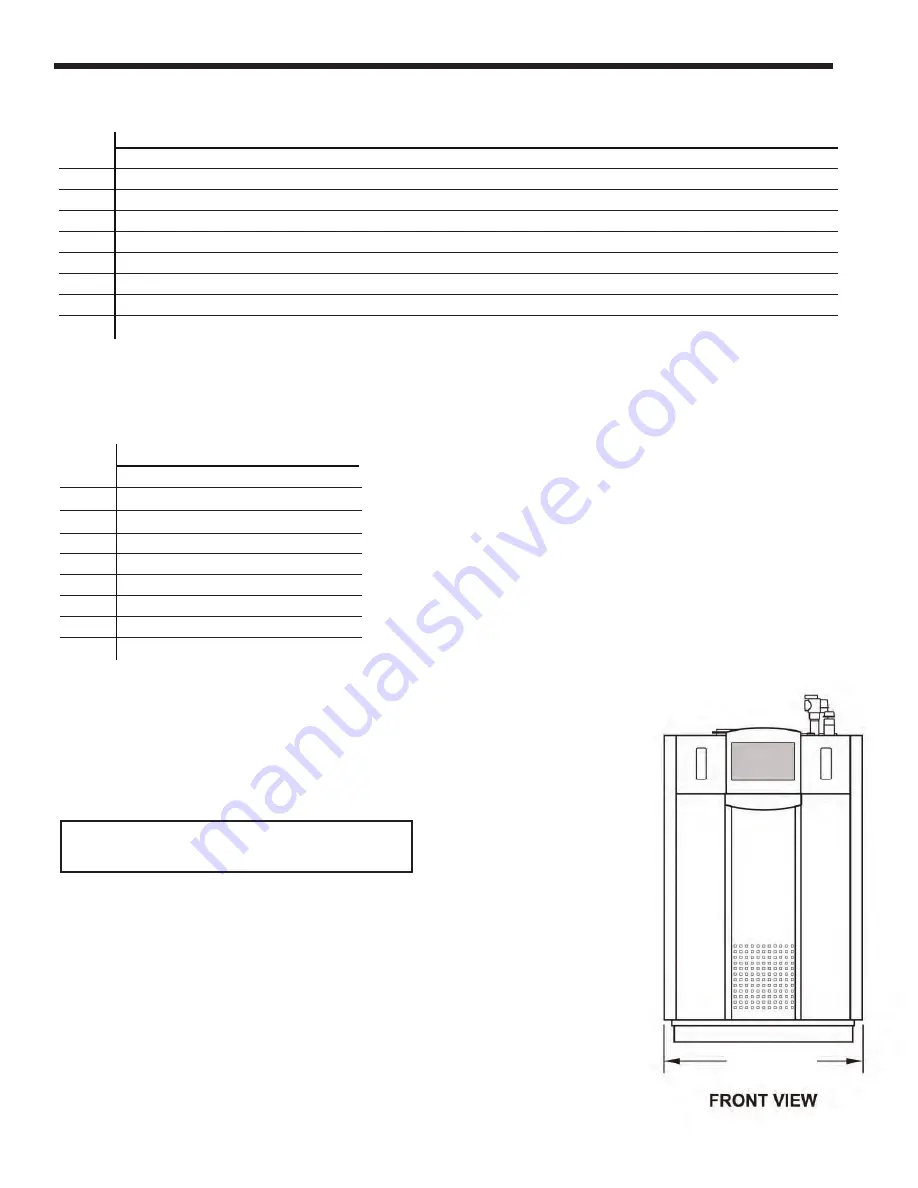
Dimension Drawing, Indoor Sizes 150-850
A
B
C
D
E
F
G
J
K
M
N
Size
in
cm
in
cm
in
cm
in
cm
in
cm
in
cm
in
cm
in
cm
in
cm
in
cm
in
cm
150
13¼
34
5¼
14
18¼
46
3¼
8
10¾
28
7½
19
14¼
36
19½
49
7½
19
15¼
39
13
33
199
20½
52
5¼
14
18¼
46
3¼
8
17¾
45
7½
19
14¼
36
19½
49
11¾
30
15¼
39
13
33
285
20¼
52
7¼
19
19½
50
6¼
16
11¼
29
13½
34
14
36
15
38
17
43
18¾
48
13
33
399
25
64
5¼
13
19½
50
4¼
11
14¾
37
18½
47
19¼
49
16½
42
21¾
55
18¾
48
13
33
500
30¼
77
5¼
13
19½
50
4¼
11
15¼
38
20
51
20½
52
19
48
26
66
18¾
48
13
33
600
29¾
76
5
13
19½
50
4¼
11
15
38
20
51
3
8
19
48
26
66
18¾
48
8¼
21
750
35½
90
6
15
19½
50
5¼
13
19
48
40½
103
3¼
8
19
48
30¾
78
18¾
48
8¼
21
850
39¾
101
6
15
19½
50
5¼
13
19
48
44¾
114
3½
9
19
48
35
89
18¾
48
8¼
21
L
AIR INLET
VENT
SIZE
in
cm
in
cm
in
cm
150
19½
49
3
7.6
3
7.6
199
26¾
68
3
7.6
3
7.6
285
26¾
68
4
11
4
11
399
31½
80
4
11
4
11
500
37¾
96
4
11
4
11
600
37¾
96
4
11
4
11
750
51
130
4
11
6
17
850
55¼
140
4
11
6
17
1.F Dimensions, Indoor Models
(length)
L
SUGGESTED SERVICE CLEARANCE
38
1/2
(98)
8
3/4
(22)
7
1/2
(19)
25
(64)
Dimensions are nominal and are shown
in inches,
cm
.
*
Unit is shipped with adapters for the air
and vent that accept standard pipe of
the proper size and type.
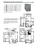
Table 1. (dimensions continued)
LAARS Heating Systems
Summary of Contents for Neotherm NTH
Page 4: ...LAARS Heating Systems...
Page 36: ...Page 36 Figure 22 Hydronic Piping Single Boiler Zoning with Circulators LAARS Heating Systems...
Page 52: ...Page 52 Figure 36 Ladder Diagram 7 H Ladder Diagram LAARS Heating Systems...
Page 100: ...Page 100 Parts Illustration 4 Internal Components Sizes 750 850 LAARS Heating Systems...
Page 102: ...Page 102 Parts Illustration 6 Gas Train Components Sizes 600 850 LAARS Heating Systems...


