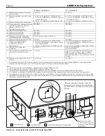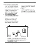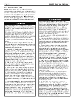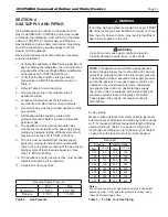
Page 42
scale buildup and failure of the heat exchanger.
6.B.3
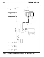
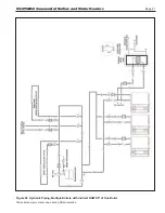
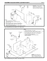
Cold Water Make-Up
The cold water make-up may be connected to the tank
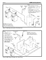
or to the inlet of the boiler as shown in Figure 29 through
Figure 32
.
Install back flow preventers and shut offs
where needed or required by code. Pipe sizes may
have to be increased to accomodate cold water make-
up flow.
6.B.4
Condensate Drain
A condensate drain trap is built into the unit.
Connect a 3/4” PVC pipe between the drain connection
and a floor drain (or a condensate pump if a floor drain
is not accessible).
The condensate drain must be installed so as to prevent
accumulation of condensate. When a condensate
pump is not used, the tubing must continuously slope
downward toward the drain with no spiraling.
Consult local codes for the proper disposal method for
the condensate.
Caution
Condensate is mildly acidic (pH = 5), and may harm
some floor drains and/or pipes, particularly those
that are metal. Ensure that the drain, drainpipe,
and anything that will come in contact with the
condensate can withstand the acidity, or neutralize
the condensate before disposal.
Damage caused by
failure to install a neutralizer kit or to adequately
treat condensate will not be the manufacturer’s
responsibility.
6.B.5
Freeze Protection
These units are certified for outdoor use but they should
not be subjected to freezing temperatures. In an event such
as power outage, component failure or other issue when
freezing is likely, the heater and system must be drained to
avoid the risk of damage due to freezing. Glycol must
not
be
used in volume water heating applications.
6.B.6
Heater Suggested Piping Schematics
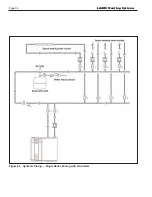
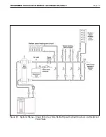
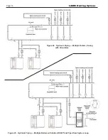
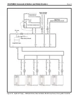
Figure 29 through Figure 32 show suggested piping
configurations for Heater boilers. These diagrams are
only meant as guides. All components or piping required
by local code must be installed.
.
SECTION 6
WATER CONNECTIONS - Part B
Section 6 is divided into two parts. Section
6A covers Boiler units designed for hydronic
heating. Section 6B covers Heater models,
which are designed exclusively for “volume
water” domestic hot water applications. Refer
to the proper section for instructions on
installing and piping your product. Refer to
Table 15 on page 34 for the connection pipe
sizes required.
6.B Water Heater
6.B.1
Water Quality
Water heaters must be installed in water conditions of
10gpg hardness or less with a pH range of 8.2 to 9.5.
Operating the Heater in water with higher hardness
levels will cause heat exchanger fouling, erosion, or
corrosion leading to premature component failure,
reduced efficiency, heat exchanger failure or system
failure. Failure of this type will not be warranted. If the
water in use exceeds the conditions recommended, a
water softener or other device should be installed to
improve water quality.
6.B.2
Piping Requirements
Water piping should be supported by suitable hangers
and floor stands. Do not support piping with the
appliance. Due to expansion and contraction of copper
pipe, consideration should be given to the type of
hangers and supports used. Rigid hangers may transmit
noise through the system resulting from piping sliding in
the hangers. It is recommended that padding be used
when rigid hangers are installed. Maintain 1” (2.5cm)
clearance to combustibles for hot water pipes.
Pipe the discharge of the relief valve (full size) to the
drain or in a manner to prevent injury in the event of
pressure relief. Install a diaphragm-type expansion
tank, flow check, and shutoff valves where needed or as
required by code.
Most water heaters can be ordered with a pump that
is sized to serve only one heater. When the pump is
included with the heater, the heater must be located
within 15 feet (4.6m) of the storage tank. The pumps
are sized for the headloss of the heater and a maximum
of 30 feet (9.1m) of piping that is the same size as the
heater water connections. See Table 15 on page 34.
If longer pipe lengths or alternate piping methods are
being used, the pump must be sized for the heater and
the piping it will serve. The manufacturer recommends
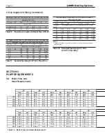
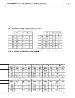
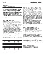
that each heater have its own pump. Table 13 shows
water flow and headloss data for the heater. Improper
pipe sizing may result in conditions that cause internal
LAARS Heating Systems
Summary of Contents for Neotherm NTH
Page 4: ...LAARS Heating Systems...
Page 36: ...Page 36 Figure 22 Hydronic Piping Single Boiler Zoning with Circulators LAARS Heating Systems...
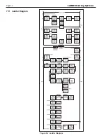
Page 52: ...Page 52 Figure 36 Ladder Diagram 7 H Ladder Diagram LAARS Heating Systems...
Page 100: ...Page 100 Parts Illustration 4 Internal Components Sizes 750 850 LAARS Heating Systems...
Page 102: ...Page 102 Parts Illustration 6 Gas Train Components Sizes 600 850 LAARS Heating Systems...

