Page 55
and asterisks will help you enter the correct number of
characters for your password.
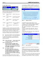
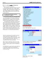
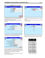
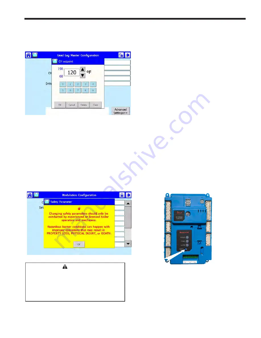
When changing a numerical value, the system
presents a numerical entry screen, as shown below.
Menu 5. Numeric Entry Screen
8.D
Verification Process for Safety-
Related Parameters
The verification process allows the user to
confirm that all the changes made are correct
and that there have not been any inadvertent
changes made.
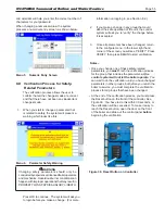
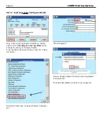
1. When you start to change a parameter that
is related to safety, the system will present a
warning which looks like this:
Menu 6. Parameter Safety Warning
WARNING
Changing safety parameters should only be
conducted by experienced, licensed boiler operators
and mechanics. Hazardous burner conditions can
happen with improper operations that may result in
PROPERTY LOSS, PHYSICAL INJURY, or DEATH.
Press OK to continue. The system will ask you
to login before you make a change. (For more
information on logging in, see Section 8.2.)
2. If you make a change in any group that could
affect the safe operation of the unit, the control
system will ask you to “verify” the change before
it is accepted.
3. Once all parameters have been changed, return
to the configure menu. In the lower right hand
corner of the screen you will see ‘VERIFY’ Press
VERIFY, then press BEGIN to start verification.
Notes –
• Once you change one of these safety-related
parameters, you
must
finish the verification process
for the group that includes the parameter,
or the
control system will not let the boiler operate
. You
can wait to do the verification until you have changed
parameters in other groups, but before you return the
boiler to service, you must complete the verification
process for all groups that have been changed.
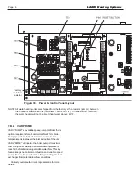
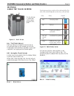
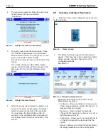
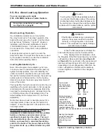
• At the end of the verification process, you must press
the Reset button on the front of the controller. See
Figure 39. You have to do this within 30 seconds, or
the verification will be cancelled. To make it easy to
reach the Reset button, open the door on the front
of the boiler and slide out the control panel
before
beginning the verification.
Figure 39. Reset Button on Controller
N
EO
T
HERM
Commercial Boilers and Water Heaters
Summary of Contents for Neotherm NTH
Page 4: ...LAARS Heating Systems...
Page 36: ...Page 36 Figure 22 Hydronic Piping Single Boiler Zoning with Circulators LAARS Heating Systems...
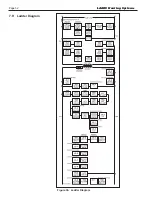
Page 52: ...Page 52 Figure 36 Ladder Diagram 7 H Ladder Diagram LAARS Heating Systems...
Page 100: ...Page 100 Parts Illustration 4 Internal Components Sizes 750 850 LAARS Heating Systems...
Page 102: ...Page 102 Parts Illustration 6 Gas Train Components Sizes 600 850 LAARS Heating Systems...

