Page 61
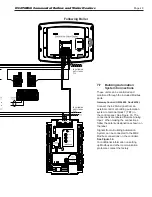
fed by 120V (violet wire) internally from the main power
feed. The System and DHW contacts are dry contacts.
Appropriate voltage must be supplied to the System
and DHW pumps for proper operation.
The System pump connections are located on terminal
block 5 (TB5) in the control panel. The System pump
contacts are rated for 120Vac, 7.4 Amps. To use the
contacts, power must be supplied on one terminal
with the other terminal wired to the pump or a relay
controlling the pump.
The DHW pump connections are located on terminal
block 5 (TB5) in the control panel and are rated for
120Vac, 7.4 Amps. To use the contacts, power must be
supplied on one terminal, and the other terminal wired
to the pump or a relay controlling the pump. Additional
120VAC circuits may be required for the pumps.
8.G.6
Demand Priority Configuration
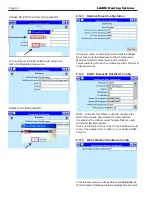
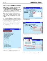
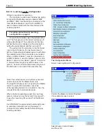
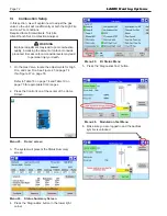
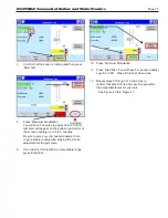
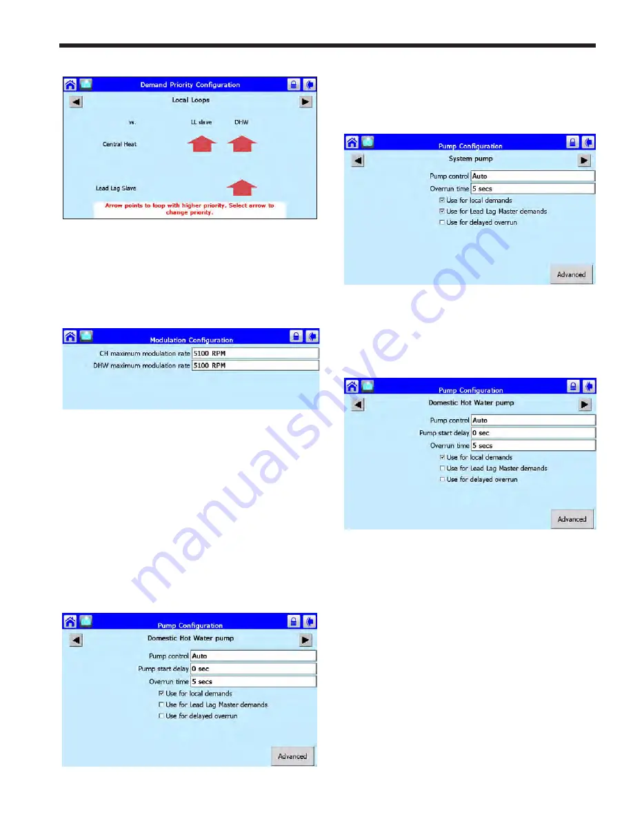
From the Demand Priority Configuration, the installer
can adjust the priority of the different demand types.
Central Heat, Lead Lag, Domestic Hot Water
The control uses arrows as indicators to point to the
loop with higher priority.
8.G.7
Modulation Configuration
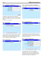
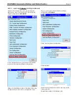
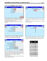
From this sub-menu the installer has the ability to adjust
the range of modulation for the CH, and DHW demands.
The unit is designed with a 5:1 turn down ratio. Any
change to the minimum and maximum modulation rates
will affect the overall ratio of the boiler. The installer
level password will allow changes to these parameters.
Consult the factory if an adjustment is needed to any of
these parameters.
8.G.8
Pump Connections
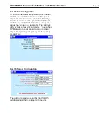
The controller in the unitenergizes the pump contacts
when it receives a call for heat. Once the call for heat is
satisfied, the pump will remain on for the defined pump
overrun time.
The Boiler Pump terminals (TB5 - max 7.4 FLA) are
N
EO
T
HERM
Commercial Boilers and Water Heaters
Summary of Contents for Neotherm NTH
Page 4: ...LAARS Heating Systems...
Page 36: ...Page 36 Figure 22 Hydronic Piping Single Boiler Zoning with Circulators LAARS Heating Systems...
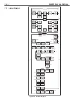
Page 52: ...Page 52 Figure 36 Ladder Diagram 7 H Ladder Diagram LAARS Heating Systems...
Page 100: ...Page 100 Parts Illustration 4 Internal Components Sizes 750 850 LAARS Heating Systems...
Page 102: ...Page 102 Parts Illustration 6 Gas Train Components Sizes 600 850 LAARS Heating Systems...

