Page 64
8.G.17 Lead Lag Follower
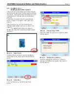
Configuration
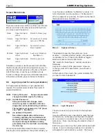
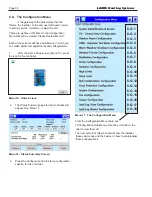
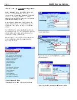
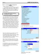
The Configuration Menu
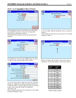
At the top select ‘System Identification & Access’
Note: The system sensor and outdoor sensor will
need to be wired to the Master boiler only.
The input from these sensors is used by the Master
control to control the modulation rate of all the
operating boilers it is connected to. See the manual
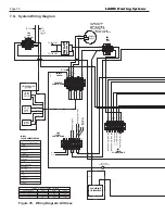
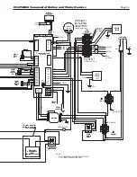
for sensor and cascade wiring.
When a boiler is operating as part of a Lead Lag
system, it does not use the normal “CH set point” –
it uses the “Lead Lag CH set point” on the Master
control.
It is STRONGLY recommended to start each boiler
to complete combustion set up and perform all safety
checks before setting up Lead Lag cascade. See
‘Combustion Setup’ in this manual.
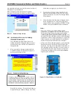
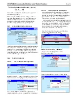
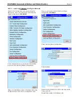
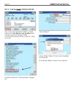
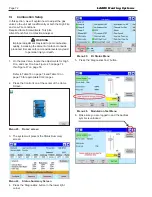
Before tapping on Lead Lag Follower Configuration
in the Configuration Menu, you must first go to
System Identification
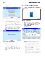
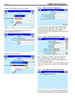
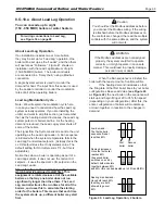
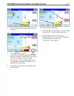
Select Boiler Name
Type in the correct name for this following boiler,
then scroll down.
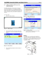
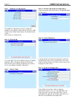
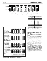
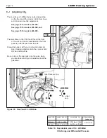
Type in the Modbus address for this following boiler
LAARS Heating Systems
Summary of Contents for Neotherm NTH
Page 4: ...LAARS Heating Systems...
Page 36: ...Page 36 Figure 22 Hydronic Piping Single Boiler Zoning with Circulators LAARS Heating Systems...
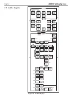
Page 52: ...Page 52 Figure 36 Ladder Diagram 7 H Ladder Diagram LAARS Heating Systems...
Page 100: ...Page 100 Parts Illustration 4 Internal Components Sizes 750 850 LAARS Heating Systems...
Page 102: ...Page 102 Parts Illustration 6 Gas Train Components Sizes 600 850 LAARS Heating Systems...

