Page 72
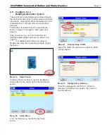
8.I
Combustion Setup
In this section, we will explain how to adjust the gas
valve so the unit will run efficiently at both the High Fire
and Low Fire conditions.
Required tools: Screwdrivers, Torx bits,
Allen Wrench Set, Combustion Analyzer
WARNING
Improper adjustment may lead to poor combustion
quality, increasing the amount of carbon monoxide
produced. Excess carbon monoxide levels may lead
to personal injury or death.
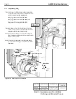
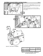
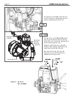
1. On the Gas Valve, locate the adjustments for High
Fire, and Low Fire.
See Figure 45 on page 74
thru Figure 47 on page 76.
Refer to Table 18 on page 74 and Table 19 on
page 75 for appropriate CO2 ranges.
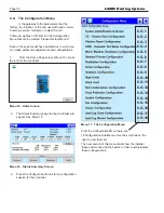
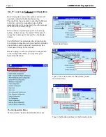
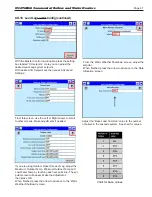
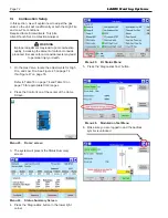
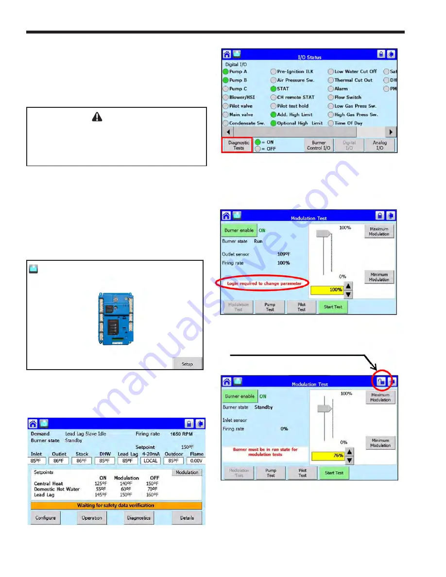
2. Press the Control Icon at the center of the Home
Screen
.
Menu 23. ‘Home’ screen
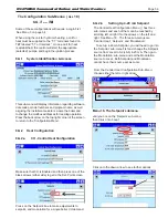
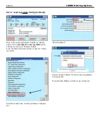
3. The system will present the Status Summary
screen.
Menu 24. Status Summary Screen
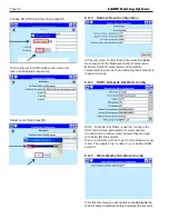
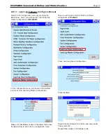
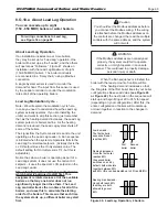
4. Press the ‘Diagnostics’ button in the lower right
corner.
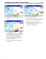
Menu 25.
I/O Status Menu
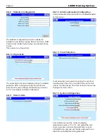
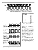
Menu 26. Modulation Test Menu
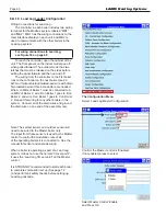
5. Press the ‘Diagnostics Test’ button.
6. Make sure you are logged in and the padlock
symbol is unlocked.
LAARS Heating Systems
Summary of Contents for Neotherm NTH
Page 4: ...LAARS Heating Systems...
Page 36: ...Page 36 Figure 22 Hydronic Piping Single Boiler Zoning with Circulators LAARS Heating Systems...
Page 52: ...Page 52 Figure 36 Ladder Diagram 7 H Ladder Diagram LAARS Heating Systems...
Page 100: ...Page 100 Parts Illustration 4 Internal Components Sizes 750 850 LAARS Heating Systems...
Page 102: ...Page 102 Parts Illustration 6 Gas Train Components Sizes 600 850 LAARS Heating Systems...

