Page 82
WARNING
Failure to rinse the debris from the heat exchanger
and temporary drain line may lead to clogged
condensate lines, traps and neutralizers.
Condensate pumps (if used) may also be damaged
by the debris left behind, possibly causing property
damage.
1. Shut off the 120 Volt power supply to the boiler
2. Turn off all manual gas valves connecting the
boiler to the main gas supply line.
3. For size 600 models only:
(All other sizes please skip to step four)
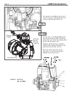
size 600 models will require the gas valve to be
removed in order to remove the burner door. To
do this, remove the wiring connections from the
gas valve. Remove the flange bolts from the gas
supply pipe connected to the gas valve (1B).
Remove the flange bolts connecting the gas
train to the Venturi (1A). Remove the gas train
assembly, and keep the gaskets and O-rings.
4. Remove the four bolts connecting the blower
flange to the burner door arm.
5. Remove the nuts located on the outside diameter
of the burner door to the heat exchanger.
6. Remove the burner door and burner assembly
from the heat exchanger.
7. Disconnect the condensate drain line.
8. Attach a longer hose to the drain and run it to a
bucket.
9. Clean the heat exchanger by brushing away
any light accumulations of soot and debris. Use
a brush with soft bristles (non metallic) to avoid
damaging the surfaces of the heat exchanger
tubes.
10. Once the tubes have been brushed clean, rinse
the tubes and combustion chamber with a small
amount of water to rinse all of the debris out of
the bottom of the flue collector and into the longer
condensate trap line. This will be diverted into
the separate container.
11. Install all components removed in the reverse
order to place the appliance back in operation. Be
sure all gaskets are in place as the components
are installed. Replace any damaged gaskets. Do
not
reuse damaged gaskets.
12. Place the appliance in operation according to
the instructions in Section 10. Check all gas
connections for leaks. Confirm that all fasteners
are tight.
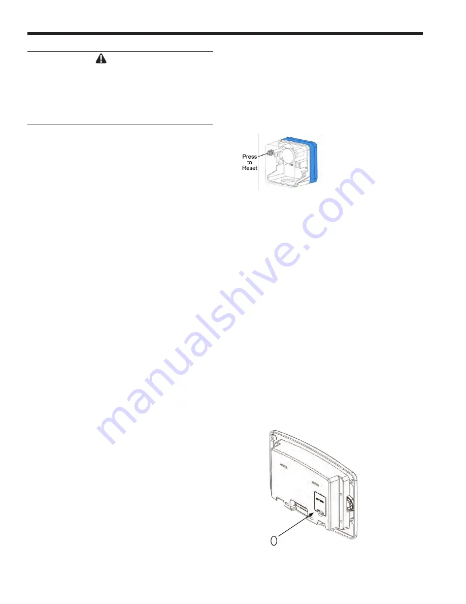
Optional Gas Pressure Switches
The high and low gas pressure switches are 24V
manual reset switches that act to cut power to the gas
valves if the gas pressure is too low or too high for
proper operation.
If your boiler is equipped with the Optional Gas
Pressure Switches, then the Low Pressure Switch will
need to be reset.
The gas pressure switches used are integrally vent
limited, and do not require venting to atmosphere. To
remove a switch, remove the screw on the plastic
housing and pull the clear cover off. Disconnect the two
wires from the screw terminals. Twist the switch off the
pipe nipple. Reassemble in reverse order. For natural
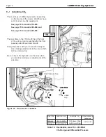
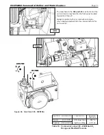
gas, set the low gas pressure switch to 3” w.c. For
propane, set the low gas pressure switch to 5” w.c. For
natural and propane, set the high gas pressure switch
to 14”.
10.C
Battery Backup for Date & Time
The touchscreen does have an internal battery for
back-up of the date and time settings. To access the
battery, the front panel and the touch screen display
must be removed so that the small plastic door on the
back of the touchscreen can be accessed.
The battery is a CR2032 ‘coin type’ battery and
has an expected service life of 10 years. If the battery
needs to be replaced, find the small plastic door on
the back of the Touchscreen Display, remove the old
battery and insert the new battery.
LAARS Heating Systems
Summary of Contents for Neotherm NTH
Page 4: ...LAARS Heating Systems...
Page 36: ...Page 36 Figure 22 Hydronic Piping Single Boiler Zoning with Circulators LAARS Heating Systems...
Page 52: ...Page 52 Figure 36 Ladder Diagram 7 H Ladder Diagram LAARS Heating Systems...
Page 100: ...Page 100 Parts Illustration 4 Internal Components Sizes 750 850 LAARS Heating Systems...
Page 102: ...Page 102 Parts Illustration 6 Gas Train Components Sizes 600 850 LAARS Heating Systems...

