Page 95
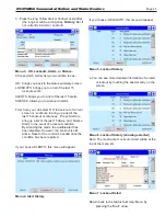
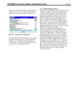
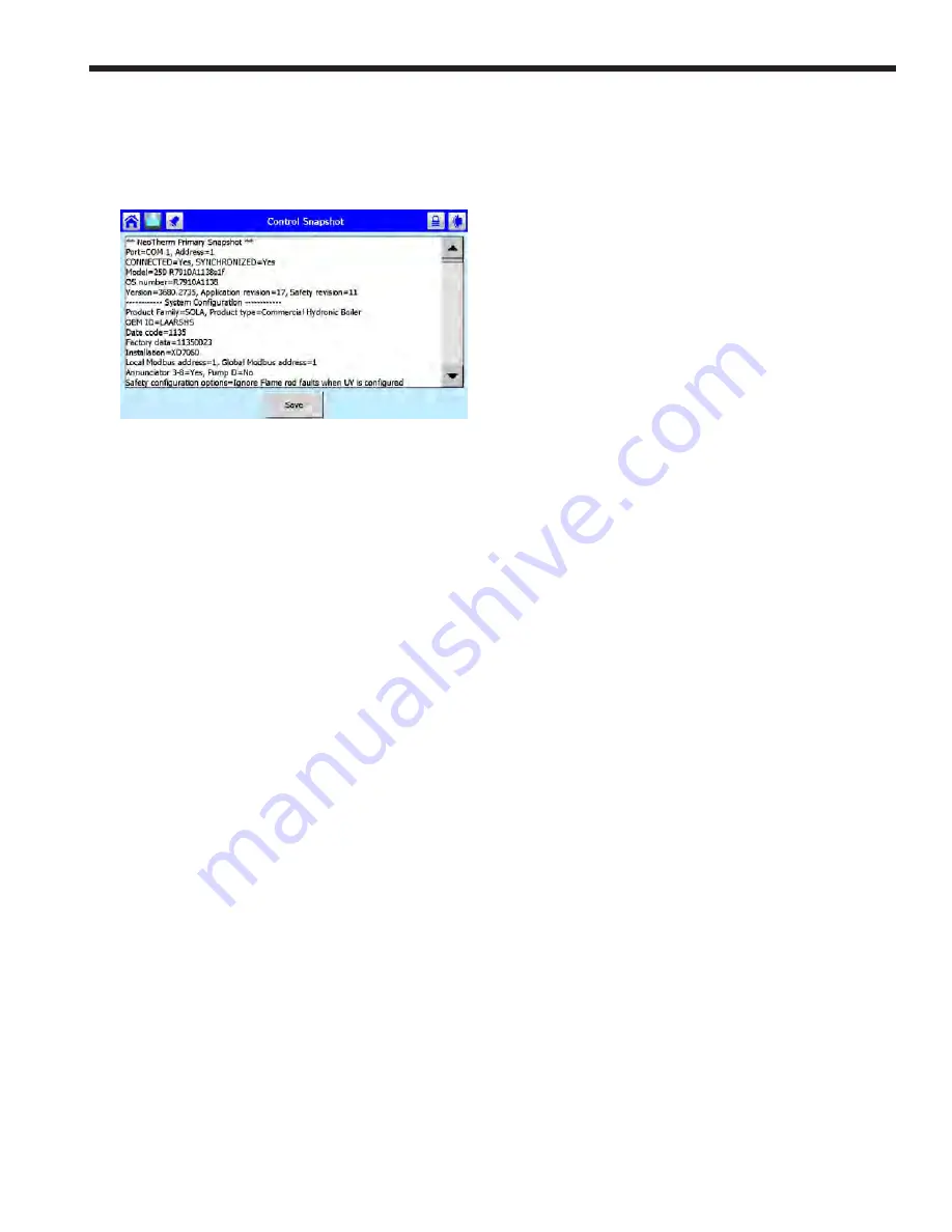
Select one of the controllers listed on the right side
of the screen. Press one of the buttons below the
right column to see the snapshot. See Menu 18.
Menu 18. Typical Control Snapshot
The Show Status button captures the current status
of the I/O of the control only. Show Confi guration
captures the current parameter settings and the
control setup. You can save the snapshot, give it a
name, or send a copy to the USB port.
11.H Operating Sequence
When there is a call for heat, the unit will close pump
contacts to energize the customer supplied relay/
contactor to start water fl ow. Once the LCI circuit
(fl ow switch, gas pressure switches, LWCO, and
High Limit aquastats) are completed the unit will
start the blower and begin the ignition sequence.
The unit is equipped with a low and high fi re air
pressure switch. The unit will pre-purge at 65% fan
for 30 seconds and prove fan through the blocked
intake switch. Once fan is proven, the blower will
proceed to 24% and the 10 second Pre-ignition timer
will begin to make the ignitor spark.
Once the Pre-ignition timer has expired the
control will open the Pilot solenoid and the Pilot
Flame Establishing Period (PFEP) will start for 10
seconds to establish fl ame. Once fl ame has been
established and the 10 second timer has expired
the control will open the main valve and the Main
Flame Establishing Period will begin for a period of
5 seconds. If fl ame is established within those 5
seconds then unit will proceed to Run, if fl ame does
not establish the unit will post-purge to 100% for
30 seconds and the sequence for ignition will begin
again. For Non CSD-1 units retry for ignition is 3
times before Lockout 109 (Ignition Failure) occurs.
For CSD-1 units there is a single retry before
Lockout 109 occurs.
N
EO
T
HERM
Commercial Boilers and Water Heaters
Summary of Contents for Neotherm NTH
Page 4: ...LAARS Heating Systems...
Page 36: ...Page 36 Figure 22 Hydronic Piping Single Boiler Zoning with Circulators LAARS Heating Systems...
Page 52: ...Page 52 Figure 36 Ladder Diagram 7 H Ladder Diagram LAARS Heating Systems...
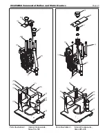
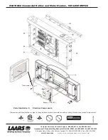
Page 100: ...Page 100 Parts Illustration 4 Internal Components Sizes 750 850 LAARS Heating Systems...
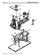
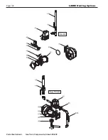
Page 102: ...Page 102 Parts Illustration 6 Gas Train Components Sizes 600 850 LAARS Heating Systems...


