LAARS Heating Systems
Page 102
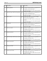
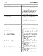
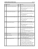
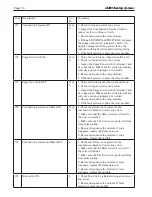
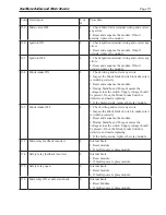
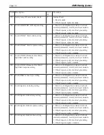
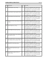
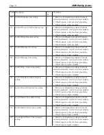
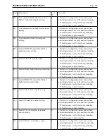
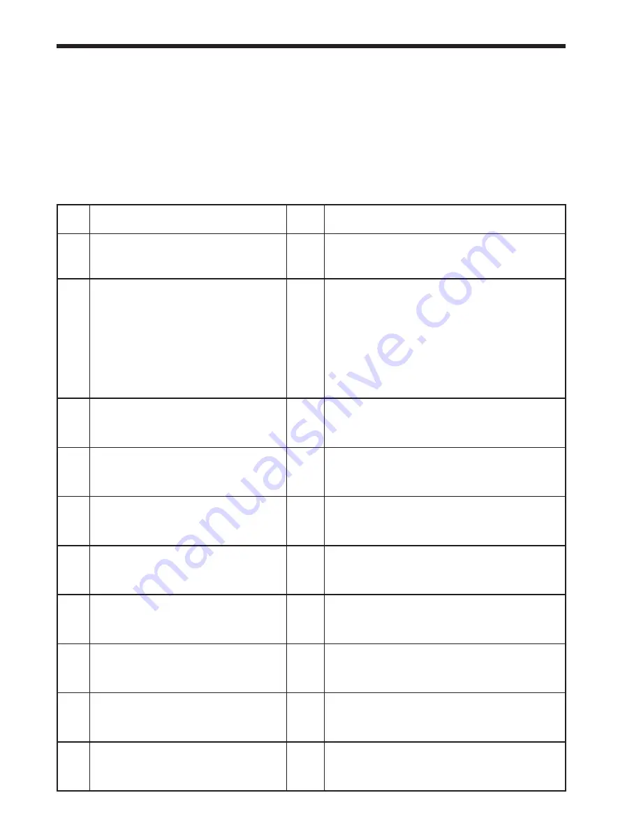
12.3 troubleshooting table
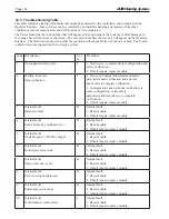
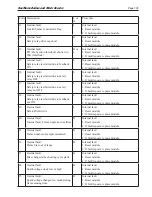
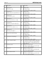
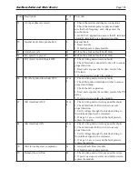
This table includes a listing of the faults that might be generated by the controllers, and displayed on the
Operator Interface. Some of these can be corrected by an installer changing a parameter, while other
conditions are more complicated, and will require a service technician.
The first column lists the code number that will appear at the beginning of the Lockout or Hold message in
the orange bar at the bottom of the screen. The second column lists the text as it will appear on the Operator
Interface. The third column shows whether the condition will cause a Hold, or Lockout, or both. The fourth
column lists some suggestions for corrective action.
Code Description
L or
H
Procedure
1
Unconfigured safety data
L
1. New device, complete device configuration and
safety verification.
2. If fault repeats, replace module
2.
Waiting for safety
data verification
L
1. Device in Configuration mode and safety
parameters need verification and a device
needs reset to complete verification.
2. Configuration ended without verification, re
enter configuration, verify safety
parameters and reset device to complete
verification.
3. If fault repeats, replace module.
3
Internal fault:
Hardware fault
H
Internal fault
1. Reset module
2. If fault repeats, replace module.
4
Internal fault:
Safety Relay key feedback error
H
Internal fault
1. Reset module
2. If fault repeats, replace module.
5
Internal fault:
Unstable power (DC DC) output
H
Internal fault
1. Reset module
2. If fault repeats, replace module.
6
Internal fault:
Invalid processor clock
H
Internal fault
1. Reset module
2. If fault repeats, replace module.
7
Internal fault:
Safety relay drive error
H
Internal fault
1. Reset module
2. If fault repeats, replace module.
8
Internal fault:
Zero crossing not detected
H
Internal fault
1. Reset module
2. If fault repeats, replace module.
9
Internal fault:
Flame bias out of range
H
Internal fault
1. Reset module
2. If fault repeats, replace module.
10
Internal fault:
Invalid burner control state
L
Internal fault
1. Reset module
2. If fault repeats, replace module.
Summary of Contents for NTV1000
Page 2: ......
Page 35: ...NeoTherm Boilers and Water Heaters Page 31 Fig 20 Ladder Diagram...
Page 36: ...LAARS Heating Systems Page 32 Fig 21 Wiring Diagram...
Page 37: ...NeoTherm Boilers and Water Heaters Page 33...
Page 51: ...NeoTherm Boilers and Water Heaters Page 47 Fig 52 Connection Terminals...
Page 130: ...LAARS Heating Systems Page 126 Fig 140 Machine Frame and Rear Panel 13 3 PARTS ILLUSTRATIONS...
Page 131: ...NeoTherm Boilers and Water Heaters Page 127 Fig 141 Front Panel and Covers...
Page 132: ...LAARS Heating Systems Page 128 Fig 142 Burners and Combustion Chambers...
Page 134: ...LAARS Heating Systems Page 130 Fig 145 Electronic Components...
Page 135: ...NeoTherm Boilers and Water Heaters Page 131 Fig 146 Condensate Trap Fig 147 Control Bezel...
Page 136: ...LAARS Heating Systems Page 132 Fig 148 Flow Switch...
Page 137: ...NeoTherm Boilers and Water Heaters Page 133 This page intentionally left blank...


