NeoTherm Boilers and Water Heaters
Page 105
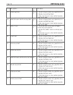
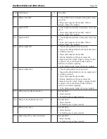
Code Description
L or
H
Procedure
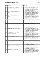
53
AC input phases reversed
L
1. Check the module and display connections.
2. Check the module power supply and make
sure that both frequency and voltage meet the
specifications.
3. On 24 VAC applications, assure that J4 terminal
10 and J8 terminal 2 are connected together.
59
Internal Fault: Mux pin shorted
L
Internal Fault.
1. Reset module.
2. If fault repeats, replace module.
61
Anti short cycle
H
Will not be a lockout fault. Hold Only.
62
Fan speed not proved
H
Will not be a lockout fault. Hold Only.
63
LCI (Limit Control Input) OFF
H
1. Check wiring and correct any faults.
2. Check Interlocks connected to the LCI to assure
proper function.
3. Reset and sequence the module; monitor the
LCI status.
4. If code persists, replace the module
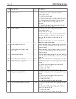
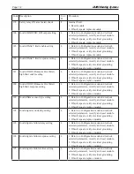
64
PII (Pre-Ignition Interlock) OFF
H or
L
1. Check wiring and correct any faults.
2. Check Preignition Interlock switches to assure
proper functioning.
3. Check the valve operation.
4. Reset and sequence the module; monitor the PII
status.
5. If code persists, replace the module.
67
ILK (Interlock) OFF
H or
L
1. Check wiring and correct any possible shorts.
2. Check Interlock (ILK) switches to assure
proper function.
3. Verify voltage through the interlock string to
the interlock input with a voltmeter.
4. If steps 1-3 are correct and the fault persists,
replace the module.
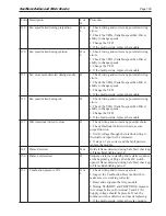
68
ILK (Interlock) ON
H or
L
1. Check wiring and correct any possible shorts.
2. Check Interlock (ILK) switches to assure
proper function.
3. Verify voltage through the interlock string to
the interlock input with a voltmeter.
4. If steps 1-3 are correct and the fault persists,
replace the module.
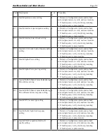
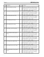
70
Wait for leakage test completion
H
1. Internal Fault. Reset module.
2. If fault repeats, replace module.
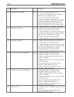
78
Demand Lost in Run
H
1. Check wiring and correct any possible errors.
2. If previous steps are correct and fault persists,
replace the module.
Summary of Contents for NTV1000
Page 2: ......
Page 35: ...NeoTherm Boilers and Water Heaters Page 31 Fig 20 Ladder Diagram...
Page 36: ...LAARS Heating Systems Page 32 Fig 21 Wiring Diagram...
Page 37: ...NeoTherm Boilers and Water Heaters Page 33...
Page 51: ...NeoTherm Boilers and Water Heaters Page 47 Fig 52 Connection Terminals...
Page 130: ...LAARS Heating Systems Page 126 Fig 140 Machine Frame and Rear Panel 13 3 PARTS ILLUSTRATIONS...
Page 131: ...NeoTherm Boilers and Water Heaters Page 127 Fig 141 Front Panel and Covers...
Page 132: ...LAARS Heating Systems Page 128 Fig 142 Burners and Combustion Chambers...
Page 134: ...LAARS Heating Systems Page 130 Fig 145 Electronic Components...
Page 135: ...NeoTherm Boilers and Water Heaters Page 131 Fig 146 Condensate Trap Fig 147 Control Bezel...
Page 136: ...LAARS Heating Systems Page 132 Fig 148 Flow Switch...
Page 137: ...NeoTherm Boilers and Water Heaters Page 133 This page intentionally left blank...


