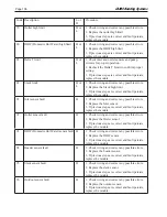
LAARS Heating Systems
Page 106
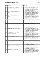
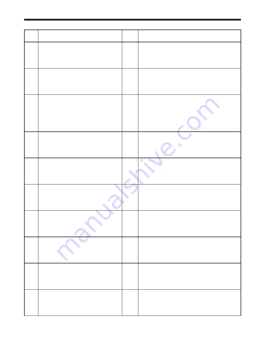
Code Description
L or
H
Procedure
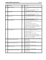
79
Outlet high limit
H or
L
1. Check wiring and correct any possible errors.
2. Replace the outlet high limit.
3. If previous steps are correct and fault persists,
replace the module.
80
DHW (Domestic Hot Water) high limit
H or
L
1. Check wiring and correct any possible errors.
2. Replace the DHW high limit.
3. If previous steps are correct and fault persists,
replace the module.
81
Delta T limit
H or
L
1. Check inlet and outlet sensors and pump
circuits for proper operation.
2. Recheck the Delta T Limit to confirm proper
setting.
3. If previous steps are correct and fault persists,
replace the module.
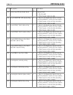
82
Stack limit
H or
L
1. Check wiring and correct any possible errors.
2. Replace the Stack high limit.
3. If previous steps are correct and fault persists,
replace the module.
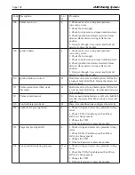
91
Inlet sensor fault
H
1. Check wiring and correct any possible errors.
2. Replace the Inlet sensor.
3. If previous steps are correct and fault persists,
replace the module.
92
Outlet sensor fault
H
1. Check wiring and correct any possible errors.
2. Replace the Outlet sensor.
3. If previous steps are correct and fault persists,
replace the module.
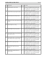
93
DHW (Domestic Hot Water) sensor fault H
1. Check wiring and correct any possible errors.
2. Replace the DHW sensor.
3. If previous steps are correct and fault persists,
replace the module.
94
Header sensor fault
H
1. Check wiring and correct any possible errors.
2. Replace the header sensor.
3. If previous steps are correct and fault persists,
replace the module.
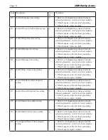
95
Stack sensor fault
H
1. Check wiring and correct any possible errors.
2. Replace the stack sensor.
3. If previous steps are correct and fault persists,
replace the module.
96
Outdoor sensor fault
H
1. Check wiring and correct any possible errors.
2. Replace the outdoor sensor.
3. If previous steps are correct and fault persists,
replace the module.
Summary of Contents for NTV1000
Page 2: ......
Page 35: ...NeoTherm Boilers and Water Heaters Page 31 Fig 20 Ladder Diagram...
Page 36: ...LAARS Heating Systems Page 32 Fig 21 Wiring Diagram...
Page 37: ...NeoTherm Boilers and Water Heaters Page 33...
Page 51: ...NeoTherm Boilers and Water Heaters Page 47 Fig 52 Connection Terminals...
Page 130: ...LAARS Heating Systems Page 126 Fig 140 Machine Frame and Rear Panel 13 3 PARTS ILLUSTRATIONS...
Page 131: ...NeoTherm Boilers and Water Heaters Page 127 Fig 141 Front Panel and Covers...
Page 132: ...LAARS Heating Systems Page 128 Fig 142 Burners and Combustion Chambers...
Page 134: ...LAARS Heating Systems Page 130 Fig 145 Electronic Components...
Page 135: ...NeoTherm Boilers and Water Heaters Page 131 Fig 146 Condensate Trap Fig 147 Control Bezel...
Page 136: ...LAARS Heating Systems Page 132 Fig 148 Flow Switch...
Page 137: ...NeoTherm Boilers and Water Heaters Page 133 This page intentionally left blank...


