LAARS Heating Systems
Page 108
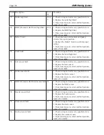
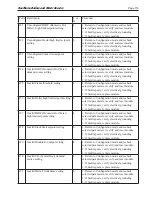
Code Description
L or
H
Procedure
108
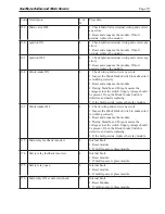
Flame lost in run
L
1. Check main valve wiring and operation -
correct any errors.
2. Check the fuel supply.
3. Check fuel pressure and repeat turndown tests.
4. Check ignition transformer electrode, flame
detector, flame detector siting or flame rod
position.
5. If steps 1 through 4 are correct and the fault
persists, replace the module.
109
Ignition failed
L
1. Check main valve wiring and operation -
correct any errors.
2. Check the fuel supply.
3. Check fuel pressure and repeat turndown tests.
4. Check ignition transformer electrode, flame
detector, flame detector siting or flame rod
position.
5. If steps 1 through 4 are correct and the fault
persists, replace the module.
110
Ignition failure occurred
H
Hold time of recycle and hold option. Will not be
a lockout fault. Hold Only. Internal hardware test.
Not a lockout.
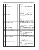
111
Flame current lower than weak
threshold
H
Hold time of recycle and hold option. Will not be
a lockout fault. Hold Only. Internal hardware test.
Not a lockout.
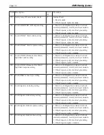
113
Flame circuit timeout
L
Flame sensed during Initiate or off cycle, hold 240
seconds, if present after 240 seconds, system will
lockout.
119
Control Interaction Fault
H
Flap valve identifications configured incorrectly.
122
Lightoff rate proving failed
L
1. Check wiring and correct any potential wiring
errors.
2. Check VFD’s (Variable-speed Fan Drive)
ability to change speeds.
3. Change the VFD
4. If the fault persists, replace the module.
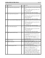
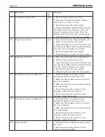
123
Purge rate proving failed
L
1. Check wiring and correct any potential wiring
errors.
2. Check VFD’s (Variable-speed Fan Drive)
ability to change speeds.
3. Change the VFD
4. If the fault persists, replace the module.
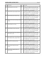
128
Fan speed failed during prepurge
H or
L
1. Check wiring and correct any potential wiring
errors.
2. Check the VFDs (Variable-speed Fan Drive)
ability to change speeds.
3. Change the VFD
4. If the fault persists, replace the module.
Summary of Contents for NTV1000
Page 2: ......
Page 35: ...NeoTherm Boilers and Water Heaters Page 31 Fig 20 Ladder Diagram...
Page 36: ...LAARS Heating Systems Page 32 Fig 21 Wiring Diagram...
Page 37: ...NeoTherm Boilers and Water Heaters Page 33...
Page 51: ...NeoTherm Boilers and Water Heaters Page 47 Fig 52 Connection Terminals...
Page 130: ...LAARS Heating Systems Page 126 Fig 140 Machine Frame and Rear Panel 13 3 PARTS ILLUSTRATIONS...
Page 131: ...NeoTherm Boilers and Water Heaters Page 127 Fig 141 Front Panel and Covers...
Page 132: ...LAARS Heating Systems Page 128 Fig 142 Burners and Combustion Chambers...
Page 134: ...LAARS Heating Systems Page 130 Fig 145 Electronic Components...
Page 135: ...NeoTherm Boilers and Water Heaters Page 131 Fig 146 Condensate Trap Fig 147 Control Bezel...
Page 136: ...LAARS Heating Systems Page 132 Fig 148 Flow Switch...
Page 137: ...NeoTherm Boilers and Water Heaters Page 133 This page intentionally left blank...


